Information processing apparatus, operation prediction method, and operation prediction program

a technology of information processing apparatus and operation prediction method, which is applied in the direction of electric digital data processing, instruments, computing, etc., can solve the problems of not being able to respond to input operations in time, take some time to confirm, and increase the processing load of information processing apparatus, so as to improve the responsiveness to input operations and shorten the period , the effect of shortening the period

Active Publication Date: 2011-07-21
SONY CORP
View PDF16 Cites 119 Cited by
  • Summary
  • Abstract
  • Description
  • Claims
  • Application Information

AI Technical Summary

Benefits of technology

[0013]By predicting the input operation from the movement of an instruction object on or to the operation surface and starting a process corresponding to the input operation, it is possible to shorten the period from when a user actually performs the input operation to when the corresponding process ends.
[0014]According to the embodiment of the invention, by predicting the input operation from the movement of an instruction object on or to the operation surface and starting a process corresponding to the input operation, it is possible to shorten the period from when a user actually performs the input operation to when the corresponding process ends. Accordingly, the information processing apparatus, the operation prediction method, and the operation prediction program improving responsiveness to the input operation compared to those according to the related art can be embodied.

Problems solved by technology

In recent years, however, the processing load of an information processing apparatus has a tendency to increase with the increase in the amount of data processed by the information processing apparatus.
Therefore, in an information processing apparatus according to the related art, it may take some time to confirm the processing result corresponding to an input operation, for example, after the input operation on a touch panel is performed.
Thus, in the information processing apparatus according to the related art, responsiveness to the input operation may not necessarily be good.

Method used


Image

  • Information processing apparatus, operation prediction method, and operation prediction program
  • Information processing apparatus, operation prediction method, and operation prediction program
  • Information processing apparatus, operation prediction method, and operation prediction program

Examples


first embodiment

1. First Embodiment

1-1. Overview of First Embodiment

[0047]First, the overview of the first embodiment will be described. A specific example of the first embodiment will be described after the overview is described.

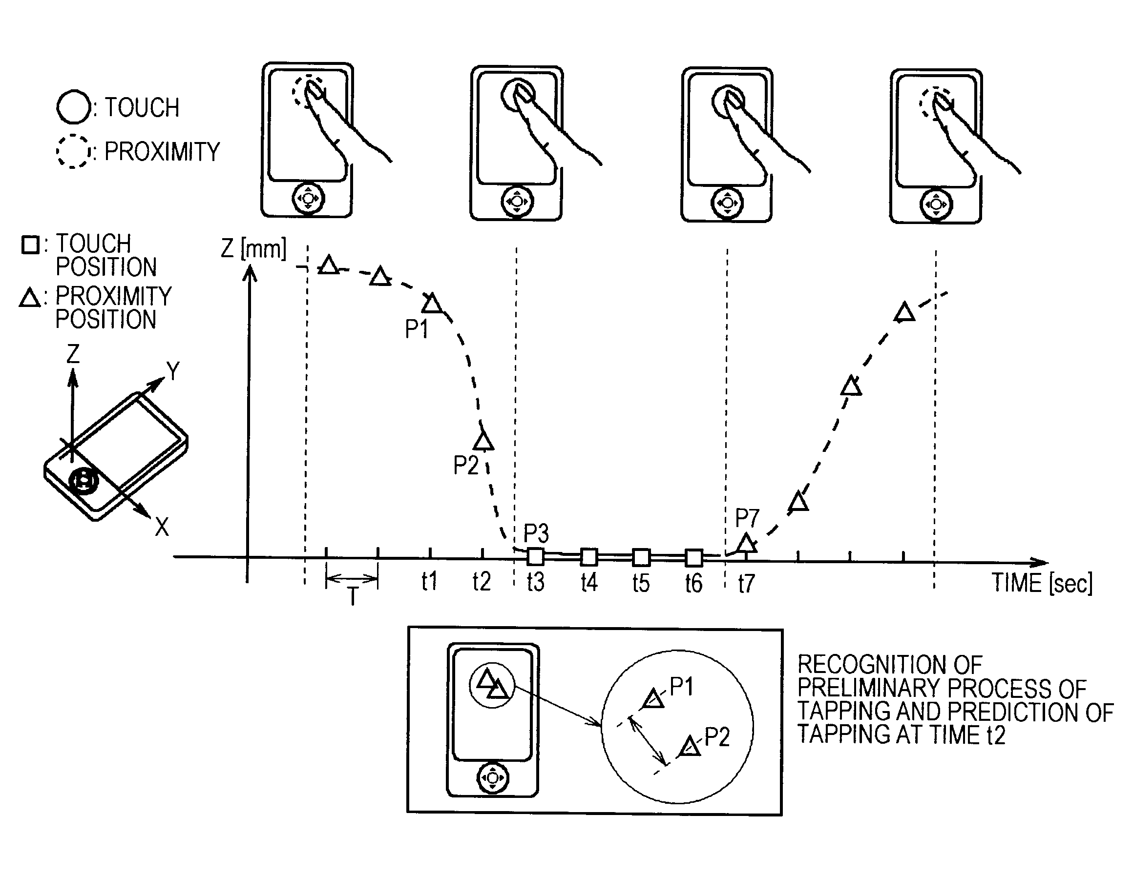
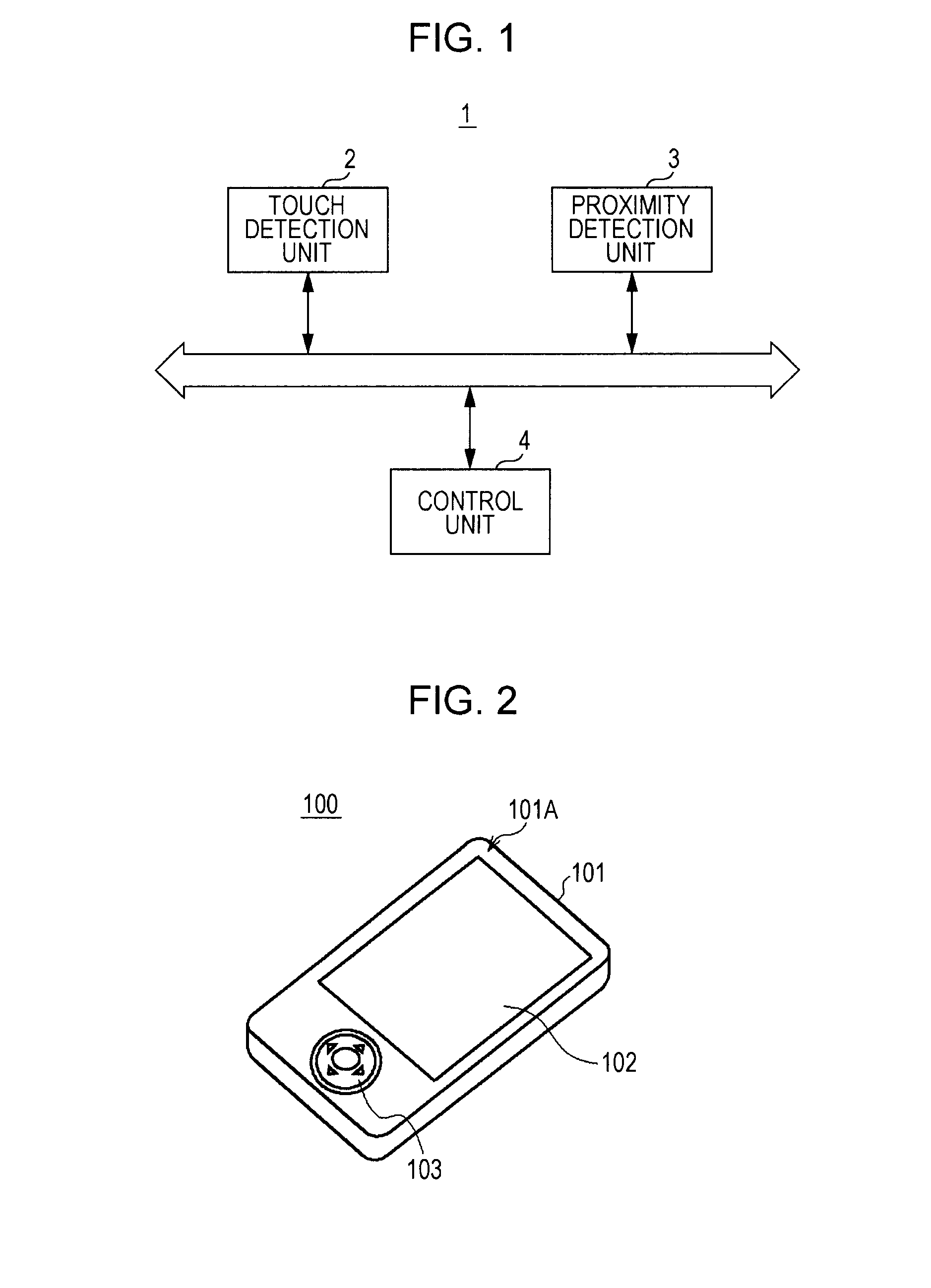
[0048]In FIG. 1, Reference Numeral 1 denotes an information processing apparatus. The information processing apparatus 1 includes a touch detection unit 2 detecting touch of an instruction object on an operation surface (for example, an operation surface of a touch panel) and a proximity detection unit 3 detecting proximity of the instruction object to the operation surface.

[0049]The information processing apparatus 1 also includes a control unit 4 which detects the movement of the instruction object on or to the operation surface based on the detection result of the touch detection unit 2 and the detection result of the proximity detection unit 3, and starts a process corresponding to an input operation predicted from the detected movement of the instruction object.

[0050]...

second embodiment

2. Second Embodiment

[0181]Next, a second embodiment will be described. In the second embodiment, a touch operation on keys is predicted when a software keyboard is displayed on the touch screen 102.

[0182]The outer configuration and the hardware configuration of the portable terminal 100 are the same as those of the first embodiment and thus will be described with reference to the first embodiment. Hereinafter, only the prediction of a touch operation when the software keyboard is displayed will be described.

2-1. Prediction of Touch Operation

[0183]The CPU 110 of the portable terminal 100 displays a character input screen 200 shown in FIG. 13 as a screen used to input characters on the liquid crystal panel 102A.

[0184]The character input screen 200 includes a character display area 200A where input characters are displayed, a conversion candidate display area 2008 where character conversion candidates are displayed, and a key display area 200C where a software key board is displayed.

[0...

third embodiment

3. Third Embodiment

[0243]Next, a third embodiment will be described. In the third embodiment, a pressure sensor is disposed in the rear of the touch panel 102B of the portable terminal 100. The portable terminal 100 allows the pressure sensor to detect a pressure (which is also called pressing force) generated when the touch screen 102 is pushed with a finger or the like, and determines whether a push operation on the touch screen 102 is performed based on the detection of the pressure. The push operation refers to an operation of pushing a touch screen with a finger.

[0244]Hereinafter, the portable terminal 100 according to the third embodiment is referred to as a portable terminal 100x to distinguish the portable terminal 100x from the portable terminal according to the first and second embodiments.

[0245]3-1. Hardware Configuration of Portable Terminal

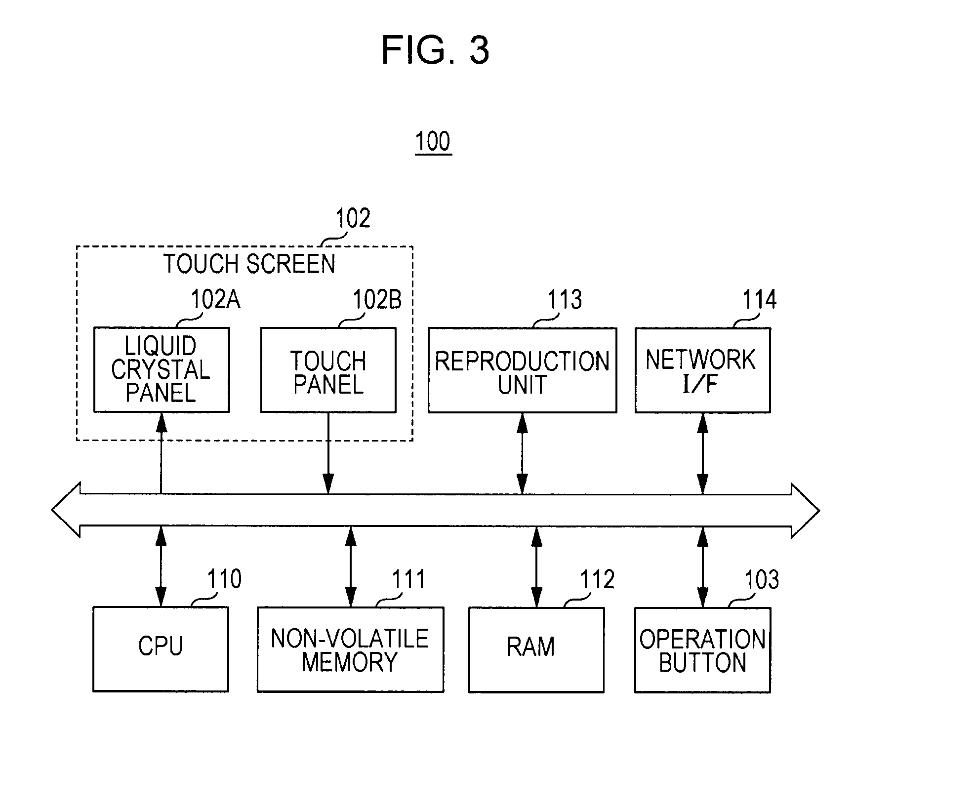
[0246]First, the hardware configuration of the portable terminal 100x will be described with reference to FIG. 17. Since the outer c...


PUM


Abstract

An information processing apparatus includes: a touch detection unit detecting touch of an instruction object on an operation surface; a proximity detection unit detecting proximity of the instruction object to the operation surface; and a control unit detecting movement of the instruction object on or to the operation surface based on the detection result of the touch detection unit and the detection result of the proximity detection unit and starting a process corresponding to an input operation predicted from the detected movement of the instruction object.

Description

BACKGROUND OF THE INVENTION[0001]1. Field of the Invention[0002]The present invention relates to an information processing apparatus, an operation prediction method, and an operation prediction program and is applicable to an information processing apparatus including, for example, a touch panel.[0003]2. Description of the Related Art[0004]In recent years, information processing apparatuses including a touch panel have come into wide use. The information processing apparatus including a touch panel detects touch of an instruction object (a finger, a touch pen, or the like) and performs various reception processes as input operations in response to the touch panel.[0005]In recent years, an information processing apparatus capable of detecting not only the touch of an instruction object on a touch panel but also a distance between the touch panel and the instruction object has been suggested (for example, see Japanese Unexamined Patent Application Publication No. 2009-116583).[0006]In...

Claims


Application Information

Patent Timeline
Patent Type & Authority Applications(United States)
IPC IPC(8): G06F3/041G06F3/0488
CPCG06F3/041G06F2203/04101G06F3/04886
Inventor MIYAZAWA, YUSUKENASHIDA, TATSUSHIHOMMA, FUMINORI
Owner SONY CORP
Why Eureka
Try Eureka