
Method and apparatus for accurate placement of ocean bottom seismic instrumentation

a technology of ocean bottom and seismic instruments, applied in mechanical equipment, instruments, pipe laying and repair, etc., can solve the problems of affecting the accuracy of data acquisition and/or costs associated with the survey, the mathematical complexity of imagining the earth in this manner, and the difficulty of accurately positioning the receiver in the marine environmen

Inactive Publication Date: 2011-07-21
FAIRFIELD INDUSTRIES INC
View PDF34 Cites 19 Cited by
  • Summary
  • Abstract
  • Description
  • Claims
  • Application Information

AI Technical Summary

Benefits of technology

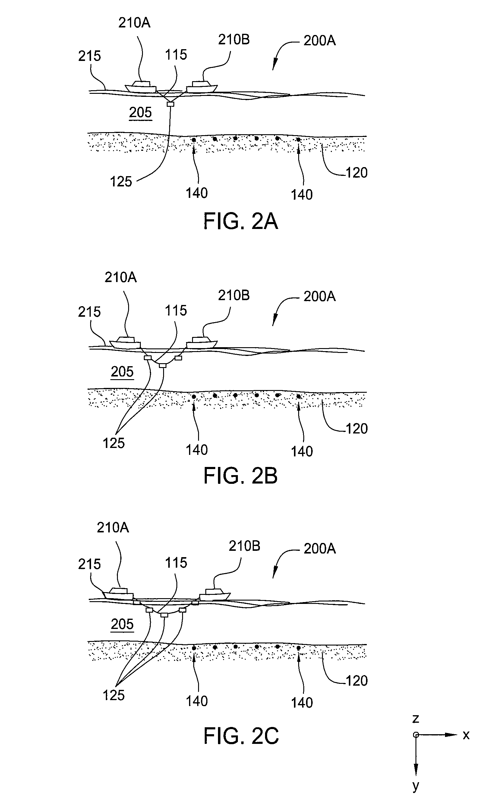
[0012]In another embodiment, a system for deploying and positioning ocean bottom equipment is described. The system includes at least a first support craft and a second support craft operating from or above a surface of a water column, at least one cable dispo

Problems solved by technology

Imaging the earth in this manner is mathematically complex and requires accurate information regarding the source and receiver locations that produced these data.
Some conventional methods used to accurately position receivers in marine environments create numerous challenges.
However, these conventional systems suffer from numerous challenges that affect accuracy in data acquisition and / or costs associated with the survey.
However, OBC and telemetry systems must carry data to the surface by wire or fiber and rough sea states can create noise problems, equipment malfunction and breakage.
Very deep water adds to these challenges as electrical connections under extreme hydrostatic pressure have a propensity to leak, which may interfere with signal and power transmission.
For these reason OBS systems are typically limited to surveys in less than 100 meters of water.
However, conventional deployment methods of the SSR devices do not always result in accurate placement of the SSR devices on the seafloor.
However, the use of ROV's is expensive and time consuming.

Method used


Image

  • Method and apparatus for accurate placement of ocean bottom seismic instrumentation
  • Method and apparatus for accurate placement of ocean bottom seismic instrumentation
  • Method and apparatus for accurate placement of ocean bottom seismic instrumentation

Examples


Embodiment Construction

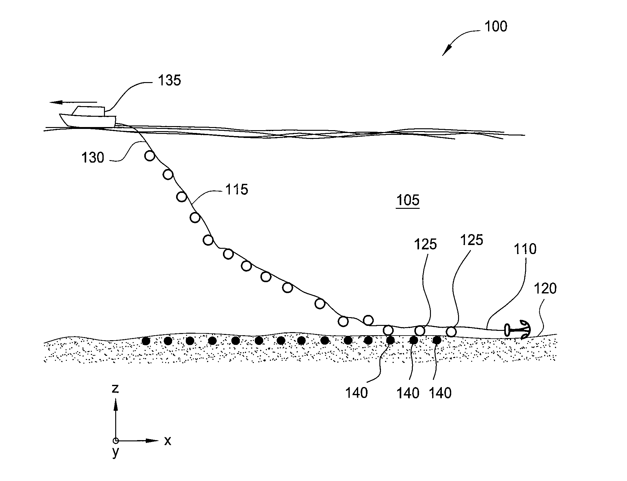
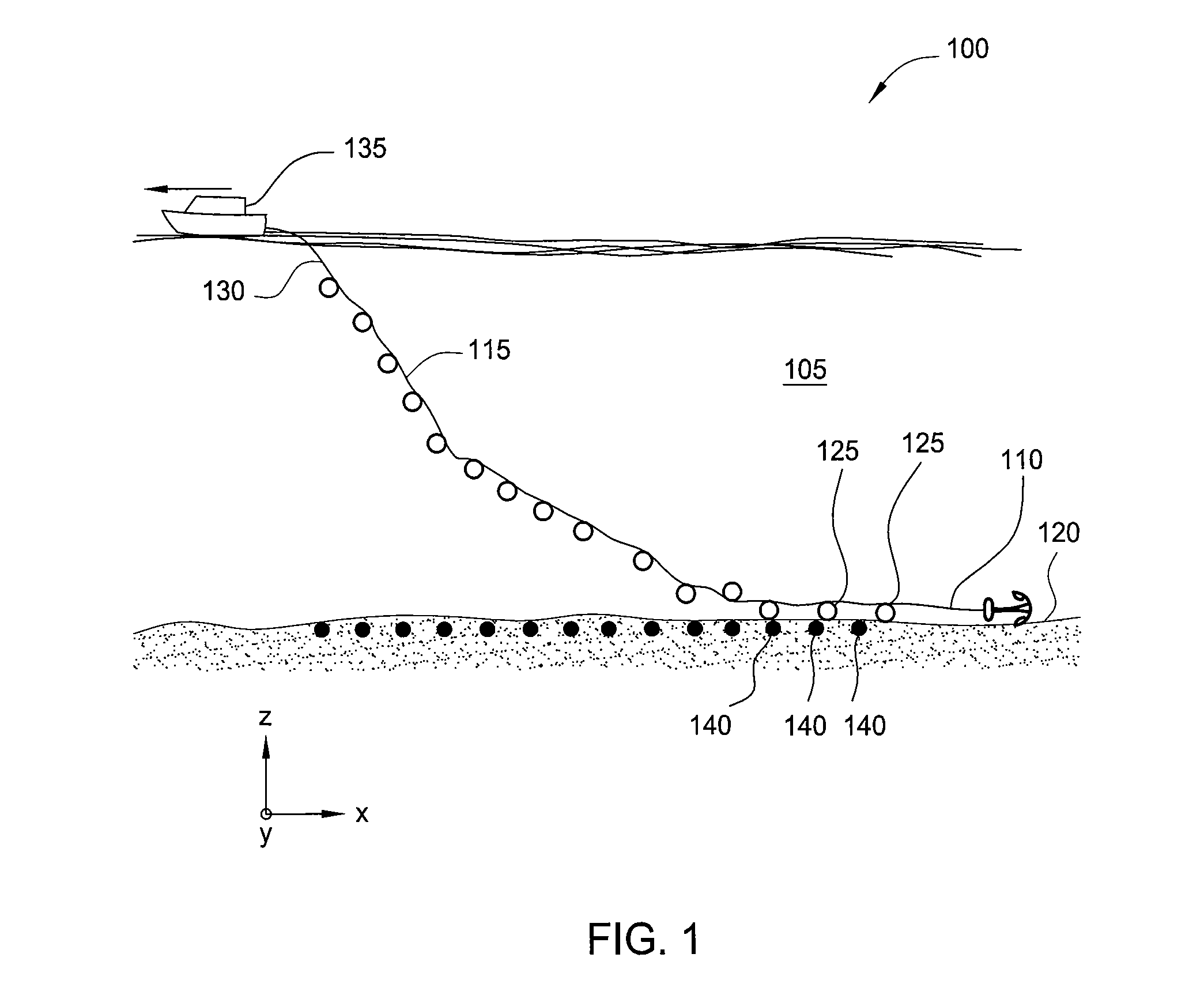
[0025]Embodiments described herein relate to an apparatus and method for transferring one or more seismic devices to or from a support craft on or near a surface of a body of water and a subsurface marine location. Seismic devices as used herein include but are not limited to seismic sensor devices whether cabled or autonomous, navigation and location instrumentation, buoyancy devices, whether positively or negatively buoyant, retrieval support mechanisms, deployment or retrieval machinery and similar devices. Each of the seismic sensor devices as described herein may be a discrete subsurface sensor, for example, sensors and / or recorders, such as ocean bottom seismometers (OBS), seafloor seismic recorders (SSR), and similar devices. SSR's are typically re-usable and may be recharged and serviced before re-deployment. The seismic sensor devices may be configured to communicate by wireless connections or configured to communicate through cables. The seismic sensor devices contain seis...


PUM


Abstract

Embodiments described herein relate to an apparatus and method for deployment and retrieval of one or more seismic devices in a deep water marine environment. In one embodiment, a method for deploying and positioning ocean bottom equipment is described. The method includes attaching at least one article having a negative buoyancy to a support cable, lowering the at least one article into the water column from two or more points of suspension on a surface of the water column, at least one of the two or more points of suspension being movable relative to the other point of suspension, and manipulating tension of the support cable, length of the support cable, position of the support cable, and distance between the two or more points of suspension to cause the at least one article to fall to a bottom of the water column at a predetermined location on the bottom.

Description

BACKGROUND OF THE INVENTION[0001]1. Field of the Invention[0002]The present invention relates generally to the field of marine seismic data acquisition, in particular to ocean bottom seismic (OBS) recording.[0003]2. Description of the Related Art[0004]Oil and gas exploration and production professionals rely heavily on seismic data in their decision making. Seismic data is collected by introducing energy into the earths surface (known as shooting or a shot), recording the subsequent reflected, refracted and mode converted energy by a receiver, and processing these data to create images of the structures beneath the surface. Imaging the earth in this manner is mathematically complex and requires accurate information regarding the source and receiver locations that produced these data.[0005]Both two-dimensional (2D) and three-dimensional (3D) seismic surveys are carefully preplanned. The planned locations for each shot and each receiver is calculated so as to achieve the geophysical o...

Claims


Application Information

Patent Timeline
IPC IPC(8): G01V1/38F16L1/12
CPCG01V1/3852
Inventor JEWELL, STEPHEN W.
Owner FAIRFIELD INDUSTRIES INC
Learn More