
Sheet Post-Processing Apparatus and Image Forming Apparatus

a post-processing apparatus and image forming technology, applied in the field of sheet post-processing apparatus and image forming apparatus, can solve the problems of difficult stacking of many booklets and awkward appearance, and achieve the effect of improving the quality of the bookl

Inactive Publication Date: 2011-07-21
CANON KK
View PDF5 Cites 5 Cited by
  • Summary
  • Abstract
  • Description
  • Claims
  • Application Information

AI Technical Summary

Benefits of technology

[0009]According to the invention, the pressing member moves at a circumferential velocity greater than a moving velocity of the moving portion on the pressing surface pressed against the booklet spine. Therefore, the pressing member does not squeeze the booklet spine downstream in the moving direction of the pressing member on the pressing surface between the booklet spine and the pressing member. The squaring process can be performed while pressing and smoothing a deformed part of the booklet spine upstream in the moving direction of the pressing member. For this reason, the booklet spine does not wrinkle. The booklet quality can be therefore improved.

Problems solved by technology

Such a booklet, when folded, easily opens at the side opposite the spine, giving an awkward appearance.
Since the booklet cannot be placed flat, it has been difficult to stack many booklets.

Method used


Image

  • Sheet Post-Processing Apparatus and Image Forming Apparatus
  • Sheet Post-Processing Apparatus and Image Forming Apparatus
  • Sheet Post-Processing Apparatus and Image Forming Apparatus

Examples


first embodiment

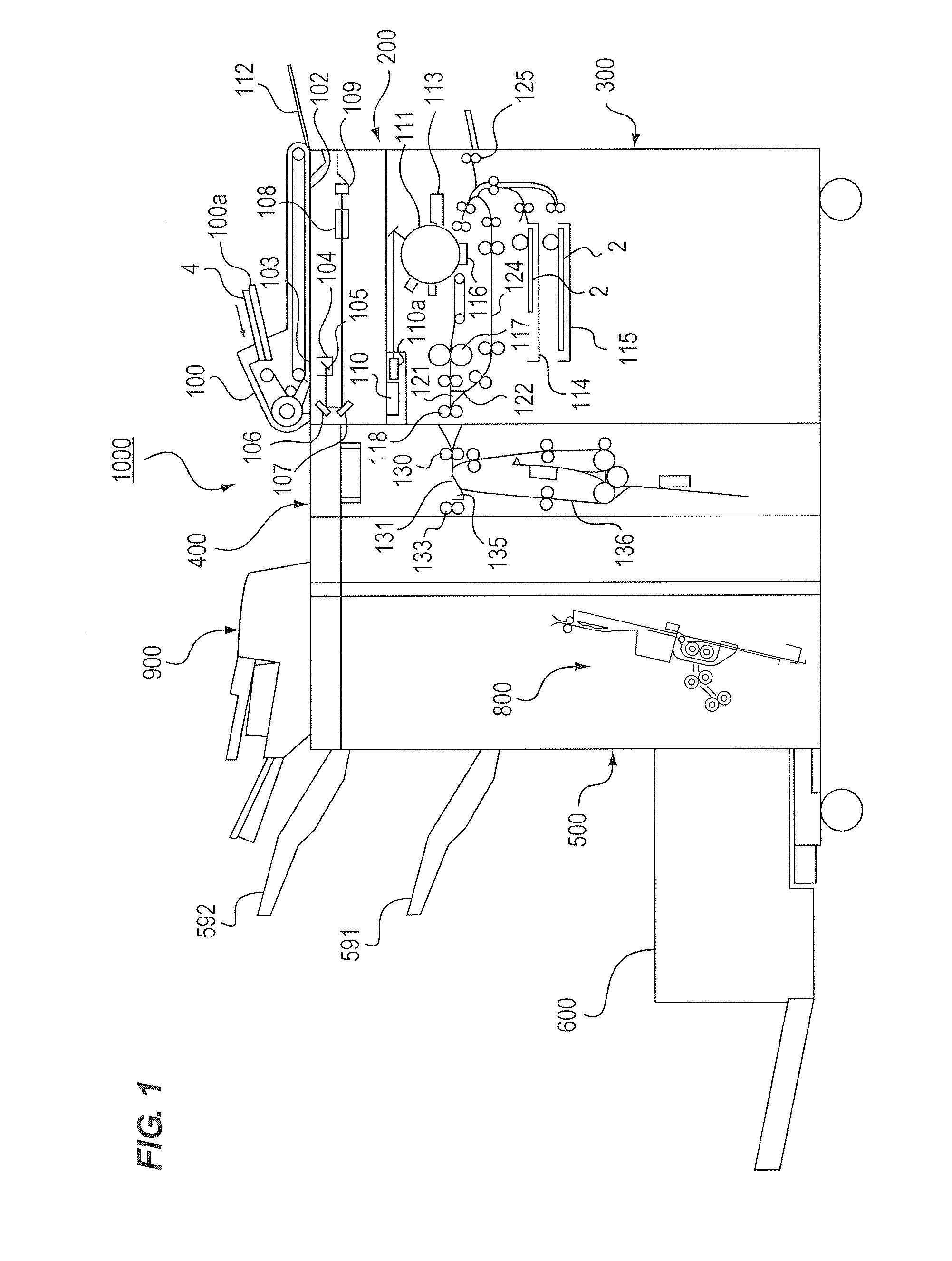
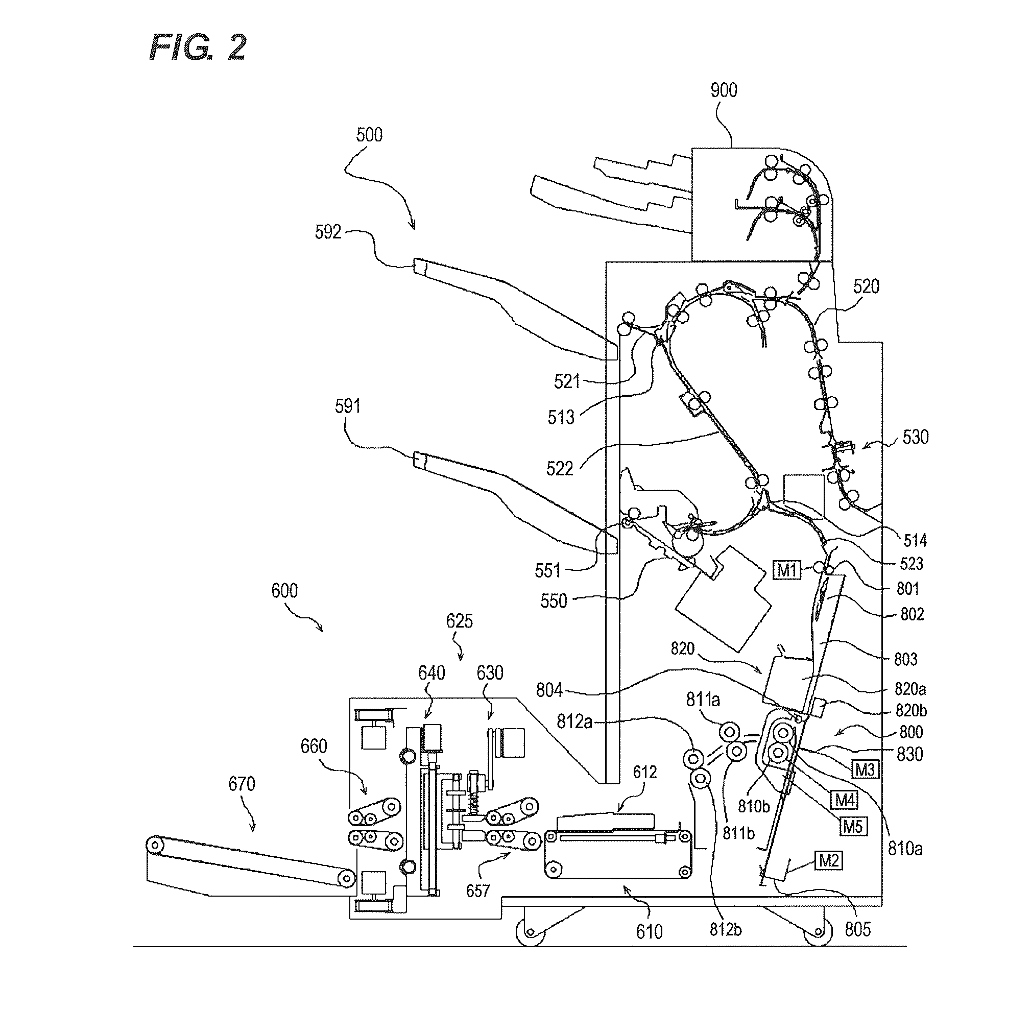
[0029]In the following, exemplary embodiments of the present invention will be described in detail with reference to the drawings. FIG. 2 illustrates essential parts of the sheet post-processing apparatus according to the invention. FIG. 1 a sectional view illustrating an internal structure of a copier 1000 as an image forming apparatus capable of using the sheet post-processing apparatus according to the invention. The copier 1000 includes a document feed portion 100, an image reader portion 200, a printer portion 300, a fold processing portion 400, a finisher 500, a saddle stitch binding portion 800 (shown in FIG. 2), a squaring processing portion 600, and an inserter 900. The fold processing portion 400, the saddle stitch binding portion 800, the squaring processing portion 600, and the inserter 900 are optional.

[0030]As illustrated in FIG. 1, a document 4 is placed in a document tray 100a of a document feed portion 100. The document feed portion 100 conveys the document 4 one sh...

second embodiment

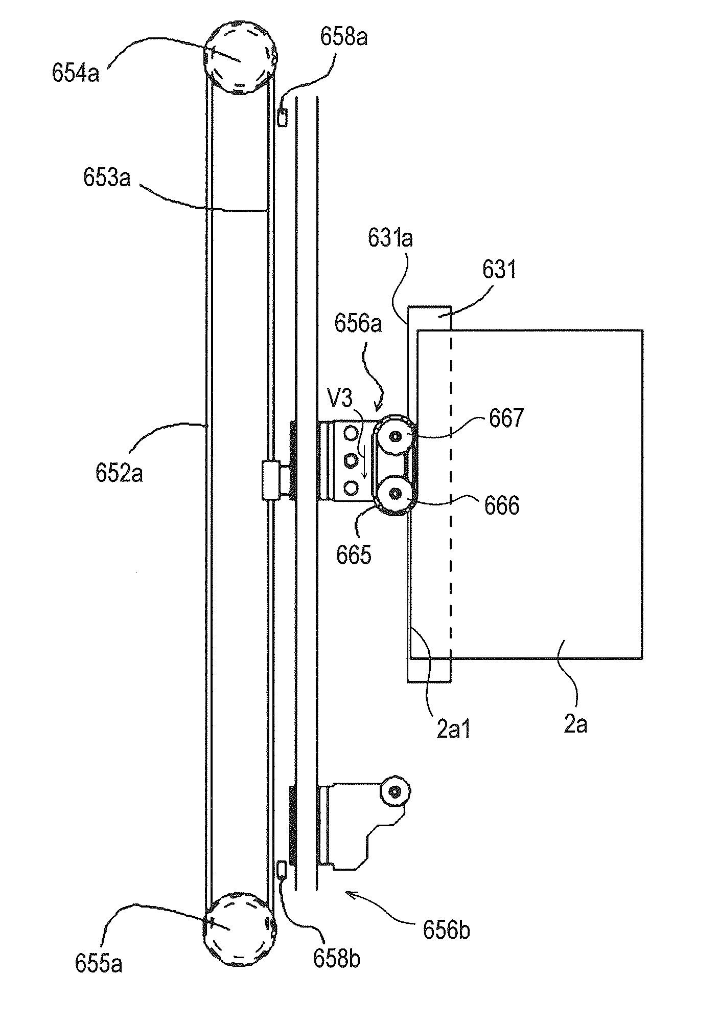
[0086]The first embodiment provides the first and second pressing members 650 and 651 using rollers. As illustrated in FIG. 16, the second embodiment uses a belt 665 as a pressing member to move along the spine 2a1 of the booklet 2a while pressing it.

[0087]The belt 665 illustrated in FIG. 16 is stretched between a drive roller 666 and a pulley 667. The drive roller 666 is driven by the drive motor SM9 as a driving portion that drives the pressing member. The drive motor SM9 as a driving portion drives the belt 665 as a pressing member. The belt 665 moves at a circumferential velocity V3 on the pressing surface where the spine 2a1 of the booklet 2a is pressed. The squaring process controlling portion 601 functioning as a controlling portion and a changing portion adjusts the circumferential velocity V3 of the pressing surface at a position where the pressing surface presses against the booklet spine 2a1 is configured so as to be reverse to and greater than the moving velocity W of th...


PUM

PropertyMeasurementUnit
Thicknessaaaaaaaaaa
Stiffnessaaaaaaaaaa
Velocityaaaaaaaaaa

Abstract

There is a need to provide a sheet post-processing apparatus capable of neatly squaring a booklet spine without any damage such as a wrinkle on the spine and an image forming apparatus having the sheet post-processing apparatus.According to the sheet post-processing apparatus, a drive motor drives first and second pressing members. A circumferential velocity of the pressing member on a pressing surface pressed against the booklet spine is configured to be reverse to and greater than a moving velocity of a moving portion.

Description

BACKGROUND OF THE INVENTION[0001]1. Field of the Invention[0002]The present invention relates to a sheet post-processing apparatus to apply post-processing to a spine of a folded sheet bundle and an image forming apparatus having the sheet post-processing apparatus. More specifically, the present invention relates to a sheet post-processing apparatus which cosmeticizes a booklet by squaring a spine of a saddle-stitch booklet.[0003]2. Description of the Related Art[0004]Conventionally, when a sheet bundle including about 20 or more sheets as a set is folded at a time, a booklet is formed having a vicinity of a spine being curved obviously. Such a booklet, when folded, easily opens at the side opposite the spine, giving an awkward appearance. Since the booklet cannot be placed flat, it has been difficult to stack many booklets.[0005]To solve this problem, U.S. Pat. No. 6,692,208 proposes a technology of pressing a swelled spine of the booklet and squaring a spine 2a1. The technology o...

Claims


Application Information

Patent Timeline
IPC IPC(8): B42C5/00
CPCB65H45/30B65H2801/27B65H2701/13212
Inventor URANO, YURI
Owner CANON KK
Learn More