Modular sub-flooring system

a subflooring system and module technology, applied in the field of sports flooring configurations, can solve the problems of high cost, high installation cost, and inability to meet the needs of sports play surfaces, and achieve the effects of facilitating controlled relative vertical movement, reducing installation cost and installation cost, and reducing installation cos

Active Publication Date: 2011-07-28
CONNOR SPORT COURT INT
View PDF83 Cites 55 Cited by
  • Summary
  • Abstract
  • Description
  • Claims
  • Application Information

AI Technical Summary

Benefits of technology

[0014]In light of the problems and deficiencies inherent in the prior art, a modular sub-flooring system is provided for supporting an overlayment above a ground surface that includes a first sub-floor tile having a first substantially-flat top surface, and a second sub-floor tile adjacent the first sub-floor tile and having a second substantially-flat top surface. The sub-flooring system also includes at least one bridge connector coupled between the first and second sub-floor tiles to facilitate controlled relative lateral movement and to restrain relative vertical movement between the sub-floor tiles, while maintaining a substantially smooth top surface alignment across adjacent edges of the first and second top surfaces.
[0015]In accordance with another embodiment described herein, a modular sub-flooring system is provided for supporting an overlayment above a ground surface that includes a plurality of sub-floor tiles situated about a ground surface, with each sub-floor tile having a substantially-flat top surface that is adapted to receive and support an overlayment, and at least one connection interface with opposing engagement surfaces. The sub-flooring system further includes a plurality of removable bridge connectors, each tile connector having a plurality of tile interfaces having complimentary engagement surfaces that engage the opposing engagement surfaces of a connection interface. The sub-floor tiles and bridge connectors are configured so that the tile interfaces of the bridge connectors couple to the respective connection interfaces of the adjacent sub-floor tiles to restrain relative vertical movement in both directions and without anchoring to ground, and facilitate controlled relative lateral movement between the adjacent sub-floor tiles.
[0017]In accordance with another embodiment described herein, a method is provided for installing an overlayment above a ground surface, which method includes installing a first sub-floor tile having a first substantially-flat top surface on a ground surface, and installing a second sub-floor tile having a second substantially-flat top surface on the ground surface adjacent the first sub-floor tile. The method also includes installing at least one bridge connector between the first and second sub-floor tiles which is adapted to facilitate controlled relative lateral movement while restraining relative vertical movement between the sub-floor tiles, and maintaining a substantially smooth top surface alignment between adjacent edges of the first and second top surfaces while allowing each sub-floor tile to individually tilt and conform to the ground surface. The method further includes installing the overlayment over the adjacent first and second top surfaces.
[0018]In accordance with yet another embodiment described herein, a method is provided for preparing a modular sub-flooring system for supporting an overlayment above an earthen ground surface. The method includes the steps of preparing an earthen ground surface to a substantially planar elevation, obtaining a plurality of sub-floor tiles, with each sub-floor tile having a substantially-flat top surface adapted to receive and support an overlayment and at least one connection interface with opposing engagement surfaces, and installing the plurality of sub-floor tiles adjacent to each other over the prepared earthen ground surface. The method also includes the steps of obtaining at least one removable bridge connector having a plurality of tile interfaces, with each tile interface having complimentary engagement surfaces that are connectable with the opposing engagement surfaces, and installing the at least one bridge connector between adjacent sub-floor tiles so that the opposing engagement surfaces interconnect with the complimentary engagement surfaces. The method further includes restraining relative vertical movement between the sub-floor tiles and allowing controlled relative lateral movement between the sub-floor tiles, while maintaining a substantially smooth top surface alignment across the plurality of sub-floor tiles despite a variation in angular orientation of any individual sub-floor tile.

Problems solved by technology

Thus, if a portion of the flooring configuration becomes damaged, it may easily be removed and replaced at a cost significantly lower than more permanent sports play surfaces.
Although traditional support bases of concrete and asphalt are commonly used, there are several inherent difficulties associated with these.
First, and foremost, these are permanent structures that require significant effort and expense to install.
In addition, once installed, it is highly impractical from a cost and labor standpoint to remove and relocated these support bases in the event one desires to transport the overriding synthetic flooring configuration to a new location.
Moreover, it is not uncommon for the support base to comprise up to one half or more of the total cost of installing a synthetic flooring configuration, particularly if the support base requires retaining or reinforcement of any kind.
This is one reason the cost for installations of synthetic flooring configurations can be high.
In the aftermath of natural disasters or other unforeseeable events, for instance, common construction materials can be in short supply, thus driving costs even higher.
In these locations, concrete must be imported, which is much too cost prohibitive and impractical in most instances for a game court.
In other countries, the technology needed to construct large slabs of concrete or asphalt is practiced or known by only a few, and equipment needed is either scarce or nonexistent.
Another significant problem centers around water drainage.
In addition to the water drainage problems, many cities and counties have limited the construction of additional concrete or asphalt slabs for various other reasons, including maintenance and liability costs.
This has significantly limited the number of play areas within certain locations, particularly in large cities where much of the landscape already comprises concrete or asphalt.
Because of these restrictions, there are often people in these areas that do not have access to a play area or sports facility.
Traditional concrete and asphalt support bases are also very rigid and hard.
They do not provide any degree of inherent flexibility or give, nor do they exhibit any impact absorption characteristics.
Furthermore, concrete and asphalt are also very susceptible to cracking.
As these slabs can often experience extreme weather conditions ranging from summer heat to winter snow, such conditions can have a detrimental effect on the concrete or asphalt surface, which can become irregular, inconsistent, and unusable over time.

Method used


Image

  • Modular sub-flooring system
  • Modular sub-flooring system
  • Modular sub-flooring system

Examples


Embodiment Construction

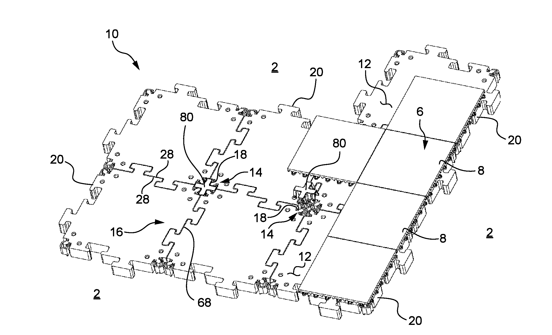
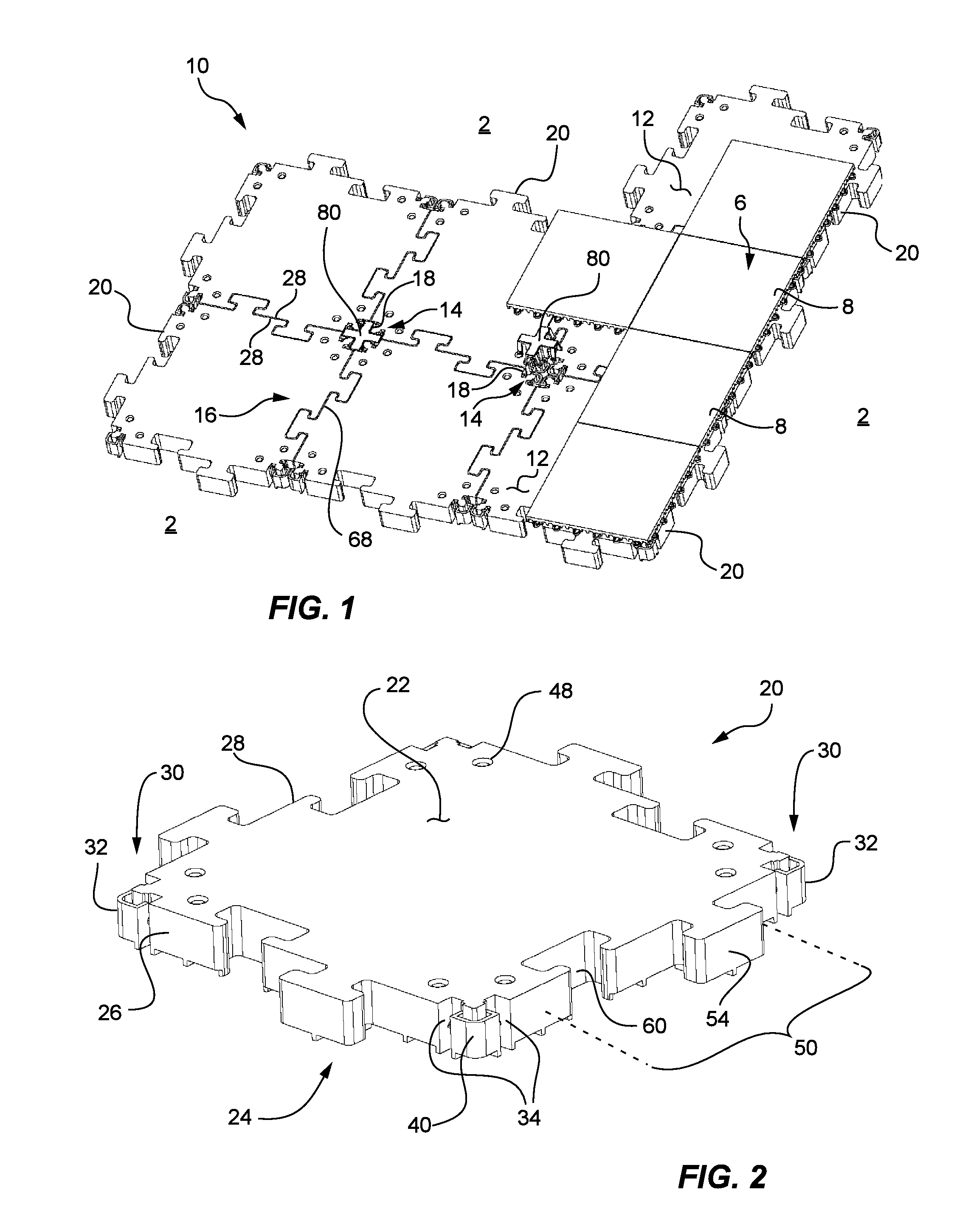
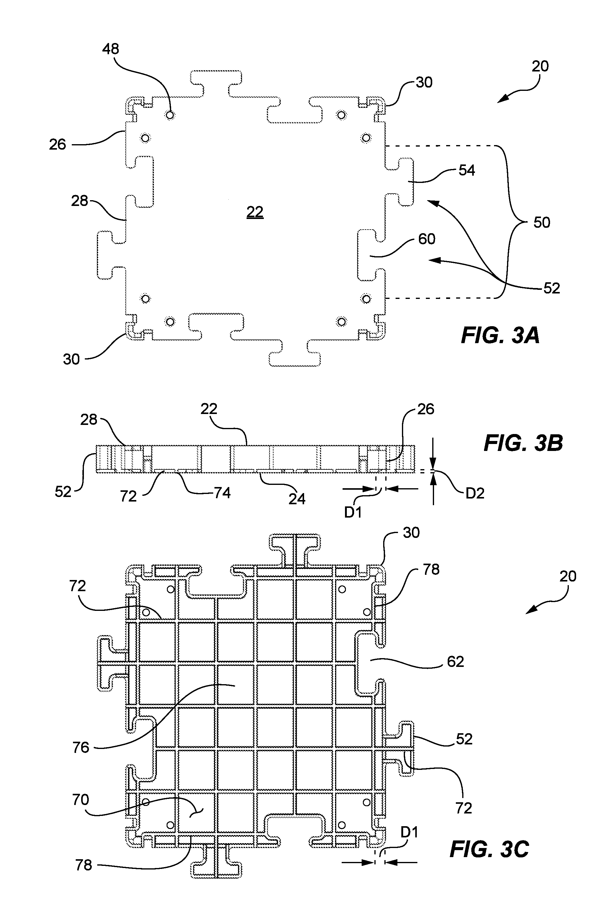
[0050]The following detailed description makes reference to the accompanying drawings, which form a part thereof and in which are shown, by way of illustration, various representative embodiments in which the invention can be practiced. While these embodiments are described in sufficient detail to enable those skilled in the art to practice the invention, it should be understood that other embodiments can be realized and that various changes can be made without departing from the spirit and scope of the present invention. As such, the following detailed description is not intended to limit the scope of the invention as it is claimed, but rather is presented for purposes of illustration, to describe the features and characteristics of the representative embodiments, and to sufficiently enable one skilled in the art to practice the invention. Accordingly, the scope of the invention is to be defined solely by the appended claims.

[0051]Furthermore, the following detailed description and...


PUM

PropertyMeasurementUnit
thermal expansionaaaaaaaaaa
vertical elevationaaaaaaaaaa
elevationaaaaaaaaaa

Abstract

A modular sub-flooring system for supporting an overlayment above a ground surface includes a plurality of sub-floor tiles situated about a ground surface, with each sub-floor tile having a substantially-flat top surface that is adapted to receive and support an overlayment, and a connection interface with opposing engagement surfaces. The sub-flooring system also includes a plurality of removable bridge connectors, with each of the bridge connectors having a plurality of tile interfaces, and with each tile interface having complimentary engagement surfaces configured to engage with the opposing engagement surfaces of the connection interfaces. The tile interfaces of the bridge connectors couple to the respective connection interfaces of any adjacent sub-floor tiles to restrain the relative vertical movement between the adjacent sub-floor tiles while facilitating controlled relative lateral movement between the sub-floor tiles.

Description

RELATED APPLICATIONS[0001]This application claims the benefit of U.S. Provisional Patent Application No. 61 / 297,510, filed Jan. 22, 2010, and entitled “Modular Sub-Flooring System”, which application is incorporated by reference in its entirety herein.FIELD OF THE INVENTION[0002]The present invention relates generally to synthetic sports flooring configurations assembled from a plurality of interlocking modular floor tiles, and more specifically to a modular sub-flooring system configured to replace the traditional concrete or asphalt slabs often used to support the synthetic sports flooring configurations.BACKGROUND OF THE INVENTION AND RELATED ART[0003]In recent years, the use of flooring configurations made of synthetic or artificial materials to form a flooring surface intended for sports play and other activities has grown in popularity. These synthetic flooring or overlayment configurations are advantageous for several reasons. For instance, they are easily manufactured and ty...

Claims


Application Information

Patent Timeline
Patent Type & Authority Applications(United States)
IPC IPC(8): E04B5/38E04F15/10E04C2/20E04G21/00E04F15/22E04B1/68
CPCE01C5/001E04F2201/095E04F2201/0138E01C13/00E04F15/02038E04F15/02194E04F15/105E04F2201/0505
Inventor CERNY, RONALD N.DAY, GARY L.HEDQUIST, DANA
Owner CONNOR SPORT COURT INT
Why Eureka
Try Eureka