
Capacitance type vibration sensor

a vibration sensor and capacitor technology, applied in the direction of electrical transducers, semiconductor electrostatic transducers, instruments, etc., can solve the problems of low frequency vibration, degrade the s/n ratio of vibration sensors (microphones), and high sensitivity degrades

Active Publication Date: 2011-07-28
MMI SEMICON CO LTD
View PDF1 Cites 19 Cited by
  • Summary
  • Abstract
  • Description
  • Claims
  • Application Information

AI Technical Summary

Benefits of technology

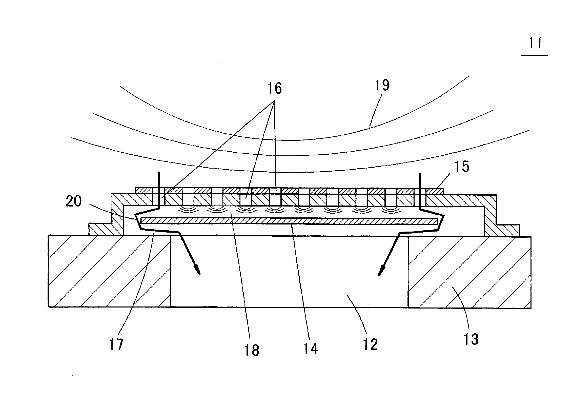
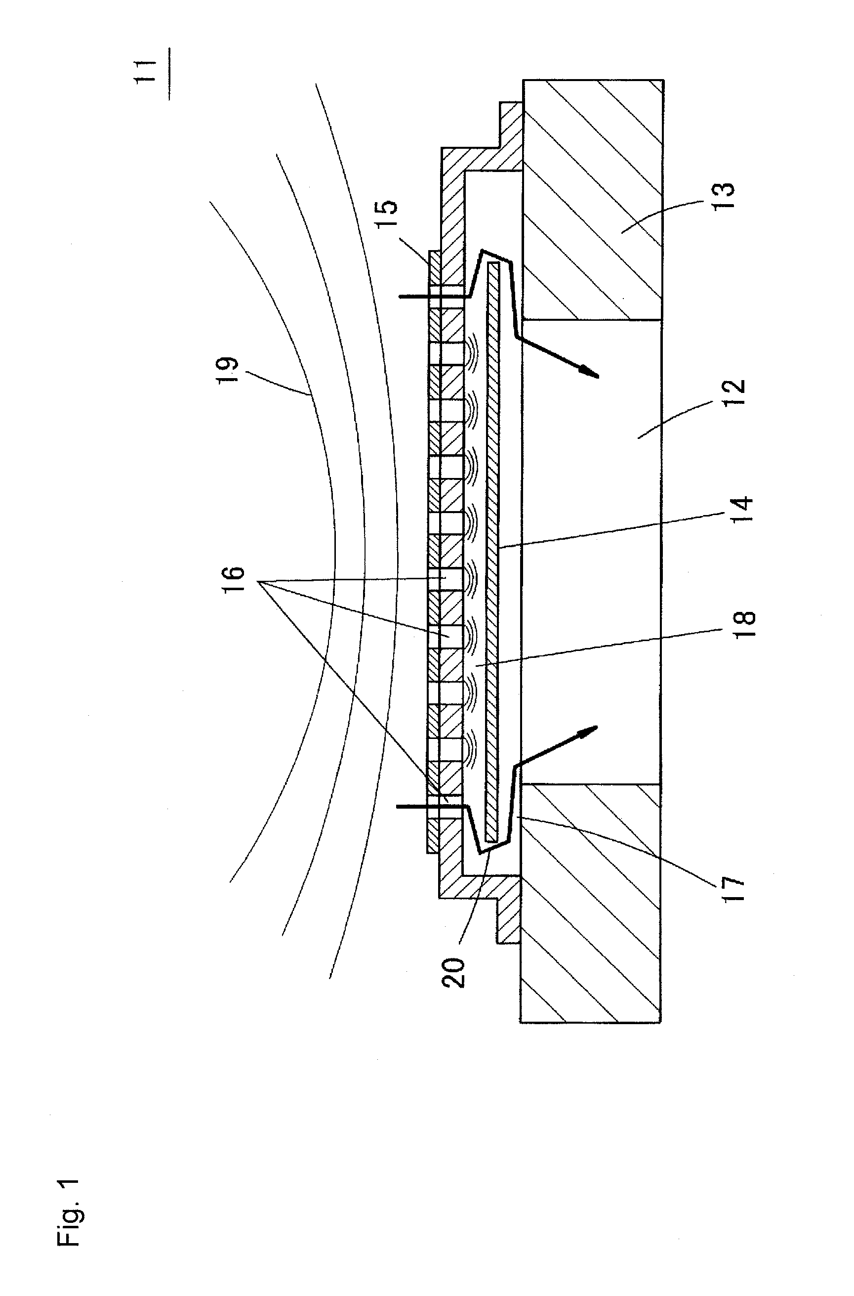
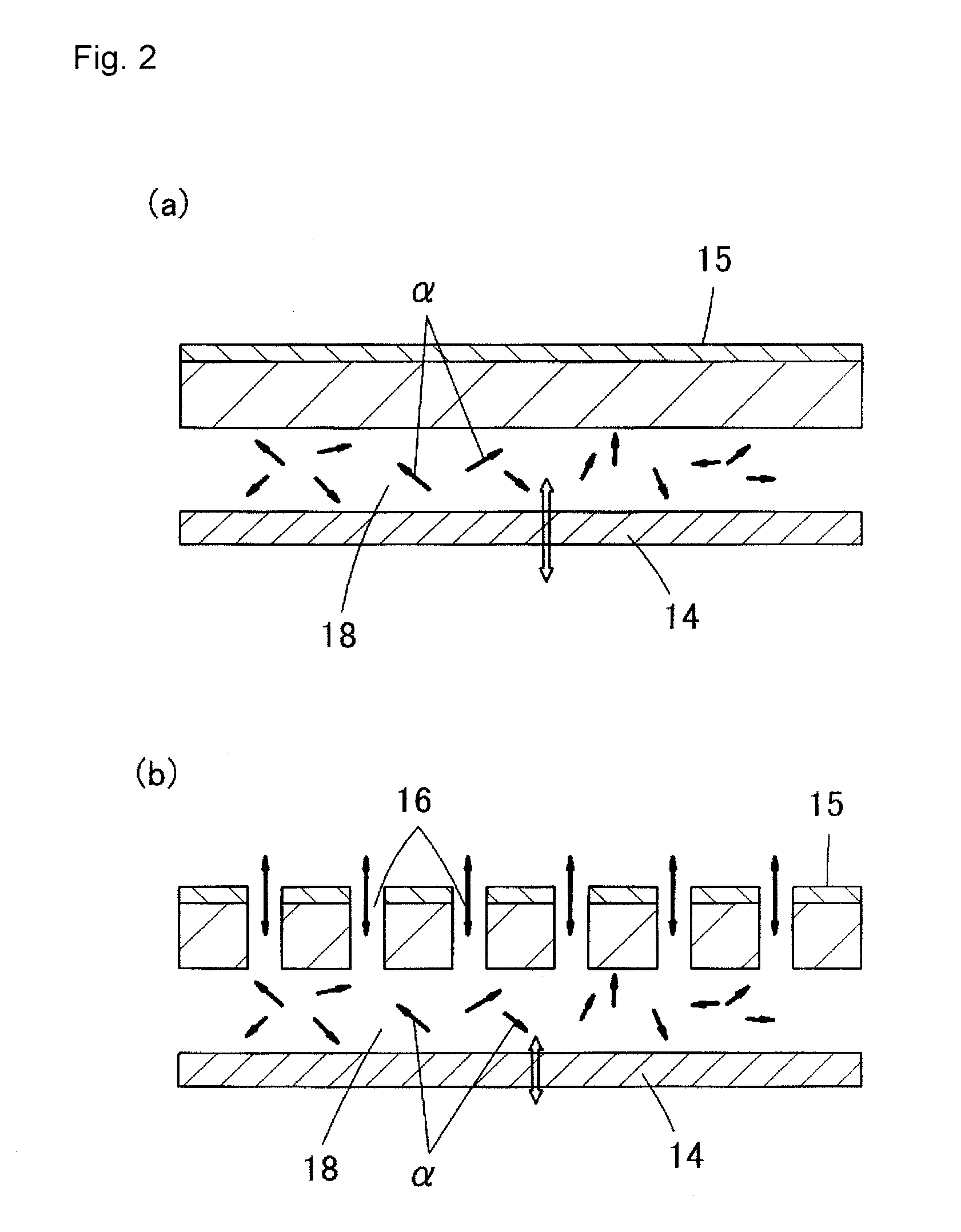
[0015]Therefore, the noise by the thermal noise in the vent hole needs to be reduced in the vibration sensor including the vent hole. The method of reducing the noise by the thermal noise includes methods of widening the gap of the vent hole, shortening the length of the vent hole in the ventilation direction, and enabling the air molecules, which become the cause of thermal noise, to easily escape from the vent hole 17.
[0039]The through-hole is desirably arranged at a position not overlapping the acoustic perforation when seen from a direction perpendicular to the vibration electrode plate. If the positions of the acoustic perforation and the air escape portion overlap each other, the low frequency vibration that entered from the acoustic perforation may easily pass through the air escape portion.

Problems solved by technology

In particular, the noise caused by such thermal noise is large and thus the S / N ratio degrades in the vibration sensor (microphone) of high sensitivity.
Furthermore, a low frequency vibration of the vibration passed through the acoustic perforation and propagated into the air gap easily leaks out to a hollow portion side through the vent hole since the low frequency vibration easily passes through the vent hole compared to the high frequency vibration.
As a result, the low frequency acoustic vibration that passes through the acoustic perforation near the vent hole leaks out to the hollow portion side without vibrating the vibration electrode plate, which degrades the low frequency characteristics of the vibration sensor.
Due to such reasons, the lower noise of the vibration sensor and the satisfactory low frequency characteristics are in the trade off relationship in the structure of the conventional vibration sensor, and it is difficult to manufacture a vibration sensor that is of low noise and that has satisfactory low frequency characteristics.
If the diameter of the through-hole or the air escape portion is larger than the diameter of the acoustic perforation, the acoustic resistance of the air path may become too small and the low frequency characteristics of the vibration sensor may degrade.

Method used


Image

  • Capacitance type vibration sensor
  • Capacitance type vibration sensor
  • Capacitance type vibration sensor

Examples


first embodiment

Variant of First Embodiment

[0068]FIG. 8 is a cross-sectional view showing, in an enlarged manner, one part of the vibration sensor according to the variant of the first embodiment. In the variant, the air escape portion 42 is arranged so that the acoustic perforation 43 and the air escape portion 42 do not overlap each other when seen from a direction perpendicular to the vibration electrode plate 34. According to one or more embodiments of the present invention, the acoustic perforation 43 and the air escape portion 42 maintain a distance of a certain degree without contacting each other when seen from the perpendicular direction.

[0069]If the air escape portion 42 is arranged so that the acoustic perforation 43 and the air escape portion 42 do not overlap each other when seen from the direction perpendicular to the vibration electrode plate 34, the path length in which the low frequency vibration reaches the air escape portion 42 such as the path γ shown in FIG. 8 becomes long. The...

second embodiment

[0071]FIG. 9(a) is an enlarged cross-sectional view showing one part of the vibration sensor according to a second embodiment, and FIG. 9(b) is a plan view showing one part of the silicon substrate 32 positioned at the periphery of the hollow portion 37. In the second embodiment, the air escape portions 51, 52 are arranged in the substrate 42 at the positions where the vent hole 45 is arranged. The air escape portion 51 is a through-hole that passes through the silicon substrate 32 in the up and down direction, and the air escape portion 51 is a bottomed recess (i.e., hole with one side blocked).

[0072]In the case of the air escape portion 51 of through-hole shape, the noise by the thermal noise can be reduced without greatly lowering the acoustic resistance of the vent hole 45, similar to the air escape portion 42 of the first embodiment.

[0073]In the case of the air escape portion 52 of recess shape as well, the distance between the bottom surface of the recess and the lower surface...

third embodiment

[0075]FIG. 10 is an enlarged cross-sectional view showing one part of a vibration sensor according to a third embodiment, and FIG. 11 is a plan view of the silicon substrate 32 used in the vibration sensor. In this embodiment, an air escape portion 61 of groove shape is provided at the upper surface of the silicon substrate 32 so as to surround the periphery of the hollow portion 37 in the vent hole 45. In the illustrated example, two air escape portions 61 are arranged, but only one may be arranged or three or more may be arranged to an extent the acoustic resistance does not become considerably small. The groove of the air escape portion 61 does not necessarily need to be annular, and a linear groove may be formed along each side.

[0076]In such embodiment as well, the noise by thermal noise in the vent hole 45 can be reduced and satisfactory low frequency characteristics can be prevented from likely lowering, similar to the first and second embodiments.

[0077]The air escape portion ...


PUM


Abstract

A capacitance type vibration sensor has a substrate including a hollow portion, a vibration electrode plate, which is arranged facing the hollow portion at an upper surface side of the substrate and which performs film vibration upon receiving vibration, and a fixed electrode plate which is arranged facing the vibration electrode plate and which is opened with a plurality of acoustic perforations passing therethrough in a thickness direction. The capacitance type vibration sensor has an air path, which communicates a space between the vibration electrode plate and the fixed electrode plate to the hollow portion, between an upper surface of the substrate and a lower surface of the vibration electrode plate in at least one part of a periphery of the hollow portion.

Description

TECHNICAL FIELD[0001]The present invention relates to capacitance type vibration sensors, and in particular, to a vibration sensor of a microscopic size manufactured using an MEMS (Micro Electro Mechanical System) technique or a micromachining technique.BACKGROUND ART[0002](Basic Structure of Vibration Sensor)[0003]FIG. 1 shows a basic structure of a capacitance type vibration sensor. A vibration sensor 11 has a vibration electrode plate 14 arranged on an upper surface of a substrate 13 having a hollow portion 12 at a central part, and an upper side of the vibration electrode plate 14 covered with a fixed electrode plate 15. A plurality of acoustic perforations 16 (acoustic holes) pass through the fixed electrode plate 15 in an up and down direction. A vent hole 17 is provided between the upper surface of the substrate 13 and the lower surface of the vibration electrode plate 14 at the periphery of the hollow portion 12, where a space (hereinafter referred to as air gap 18) between ...

Claims


Application Information

Patent Timeline
IPC IPC(8): G01H11/06
CPCH04R19/005H04R31/006H04R19/04
Inventor KASAI, TAKASHITSURUKAME, YOSHITAKA
Owner MMI SEMICON CO LTD
Learn More