Miniature sludge lance apparatus

a technology of sludge lance and miniaturization, which is applied in the direction of lighting and heating equipment, machines/engines, flush cleaning, etc., can solve the problems of inability to clean equipment, sludge between close patterns, and less effective at locations separated from the tube lane, etc., to achieve quick, accurate, repeatable setup

Active Publication Date: 2011-07-28
WESTINGHOUSE ELECTRIC CORP
View PDF9 Cites 6 Cited by
  • Summary
  • Abstract
  • Description
  • Claims
  • Application Information

AI Technical Summary

Benefits of technology

[0011]Cleaning of the tube sheet and the outer surface of the tubes, or “sludge lancing,” can be accomplished efficiently and, essentially, automatically through the inspection ports by introducing a cleaning tool, or “lance,” through the inspection penetrations that are narrower than the tube gap (the space between adjacent tubes that are a function of the tube diameter and pitch). Providing, of course, that the lance can be aligned with a tube row and that the lance may be positioned to spray the high velocity jet generally parallel to the tube sheet. The inspection port lancing system disclosed below has the capability of being automatically indexed relative to tube bundle spacing and in one embodiment includes a simulated jet oscillation feature that translates rotary-to-linear motion for a high velocity lancing head suspended at the tube sheet level. This system reduces the time required to perform the sludge lancing, thus lowering the radiological dose.
[0014]The disclosed and claimed concept further includes a segmented rail. The rail defines the passage through which the water, or other cleanser, passes prior to the nozzle assembly. The oval geometry of the water passage, and associated end seals, enables high fluid flow. Lower placement of the water passage balances the coupling loads and eliminates the need for internal support structures. The rail also includes a drive shaft structured to move the nozzle assembly. The nozzle assembly is coupled to a first end of the rail, the end that is inserted into the steam generator. A water manifold is coupled to the second end of the rail, the end that remains outside of the steam generator. Further, an oscillation assembly is disposed at the rail second end and is structured to provide motion to the drive shaft.
[0015]On one hand, it is desirable to have as few separate components inserted into the steam generator as that increases the chances of accidentally dropping a component in the steam generator. Thus, if there is only a single inspection opening, rather than opposed openings, at a certain orientation and elevation on the steam generator shell, a rail may be, essentially, as long as the diameter of the steam generator. On the other hand, steam generators are often located in confined spaces wherein an extended rail could not fit. Thus, preferably, the rail is segmented. That is, a plurality of similar rail assemblies are coupled together to form the rail. The rail assemblies may be a uniform length, thus reducing manufacturing costs, or, may be a variety of lengths so as to reduce the number of components while still being useful in a confined space. For example, rail assemblies having lengths of five, three, and two feet could be used to form a rail having a total length of ten feet, but could still be manipulated in building providing a six foot space about a steam generator.
[0019]In this configuration, the miniature sludge lance provides quick, accurate, and repeatable setup.

Problems solved by technology

This cleaning pattern, however, may leave sludge between the close pattern of tubes and is less effective at locations spaced from the tube lane.
The tube lane blocks can prohibit access for cleaning equipment through the six inch penetration.
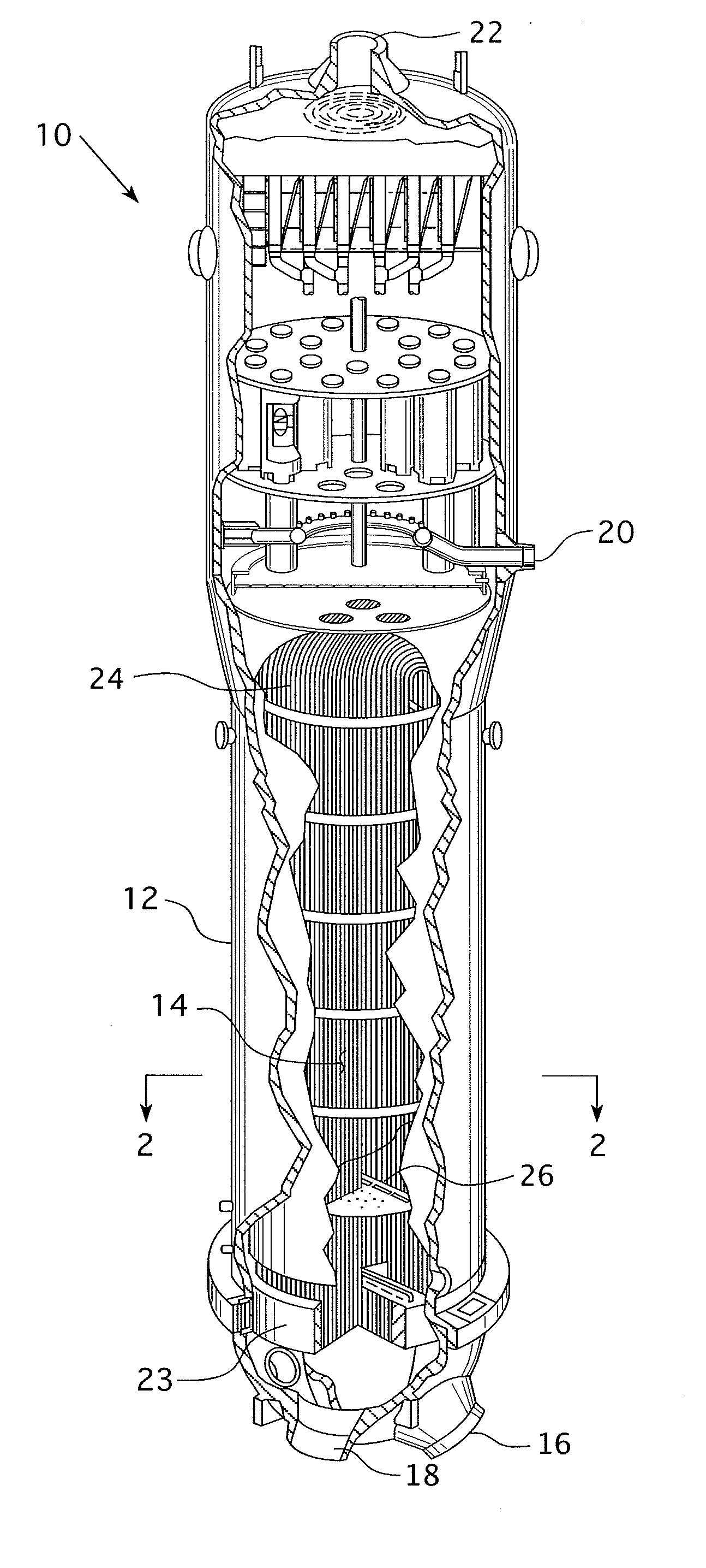
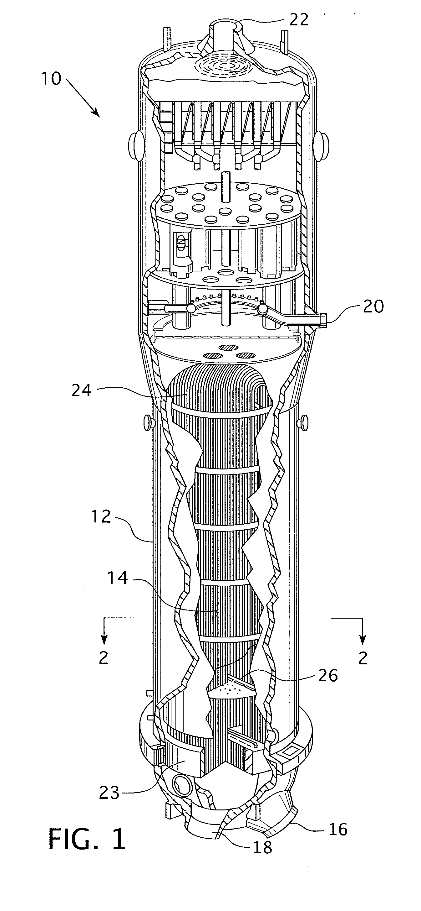
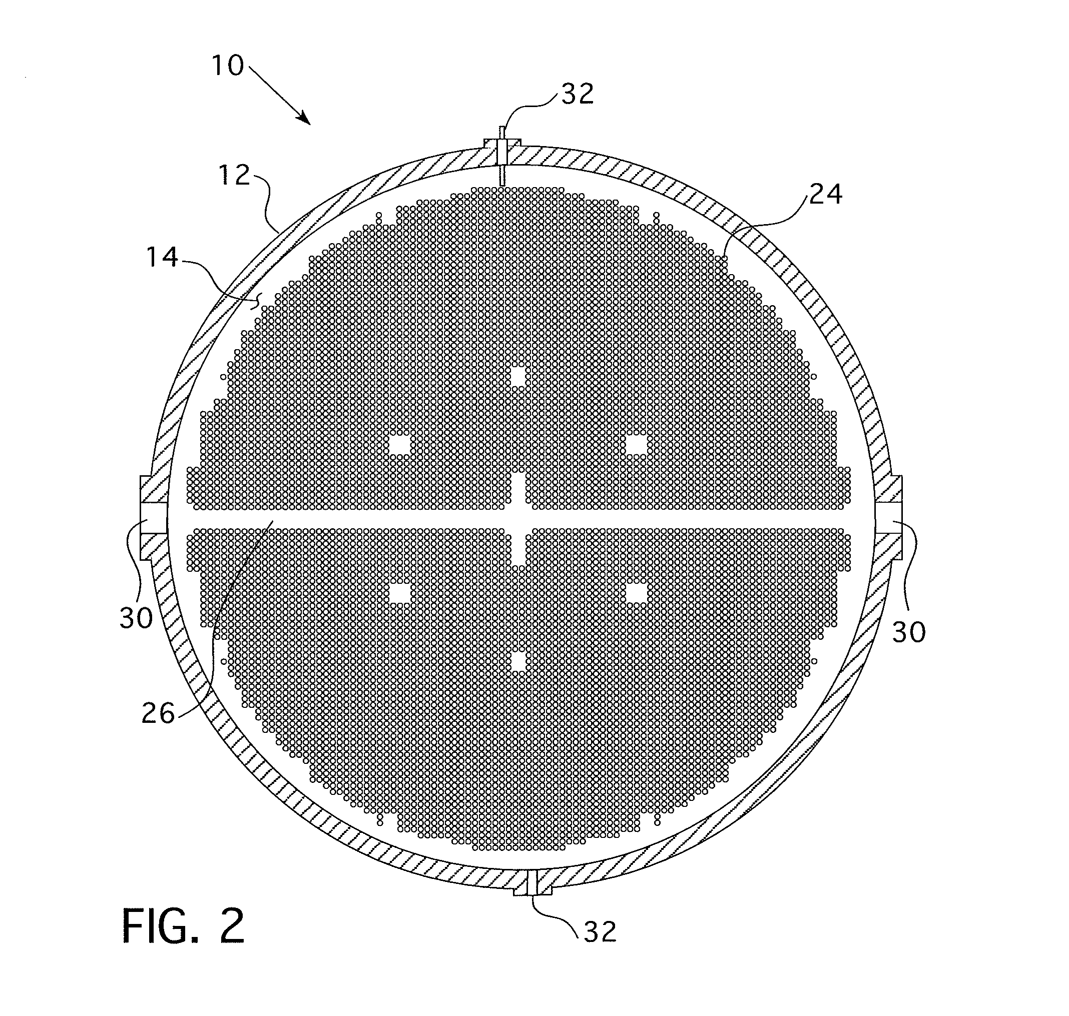
Due to various internal physical restrictions in the tube lane (the area generated along the centerline of the tube sheet by the minimum bend radius of the Row 1 tubes), the tube sheet legs (either hot or cold depending on the location of the inlet nozzle) cannot be adequately cleaned by conventional lancing equipment mounted to the hand holes.
After entrance through an inspection penetration, access is limited by the gap between adjacent tubes.
These openings are not typically used for cleaning because the problem is to accurately position and sweep high pressure cleaning jets and deliver high water volume within the confines of adjacent tube spacing and the inspection penetration.
Sludge lancing is typically not performed through these penetrations due to their physical size and location.
Therefore, the tube lane in these steam generators is basically inaccessible and prone to accumulating sludge and debris under the blowdown pipe and between the TLBD's.
In addition, certain utilities have forbidden hand-lancing with static jets that impinge directly on the tube sheet and adjacent steam generator tubing—this limits certain types of manual lancing that could be employed through the inspection penetrations to clean this region.
Sludge lancing technicians are subjected to higher doses or radiation with equipment that does not provide an automated mechanical means of oscillation or rotation of the high velocity jets down the tube gaps.
Water turbulence from a 90 degree bend significantly increases the divergence of the exiting water jet.

Method used


Image

  • Miniature sludge lance apparatus
  • Miniature sludge lance apparatus
  • Miniature sludge lance apparatus

Examples


Embodiment Construction

[0046]As used herein, “coupled” means a link between two or more elements, whether direct or indirect, so long as a link occurs.

[0047]As used herein, “directly coupled” means that two elements are directly in contact with each other.

[0048]As used herein, “fixedly coupled” or “fixed” means that two components are coupled so as to move as one while maintaining a constant orientation relative to each other. The fixed components may, or may not, be directly coupled.

[0049]As used herein, “temporarily coupled” means that two components are coupled in a manner that allows for the components to be easily decoupled without damaging the components. “Temporarily coupled” components are easy to access or otherwise manipulate. For example, a nut on a bolt that is exposed is “temporarily coupled” while a nut on a bolt within a typical transmission case sealed by multiple fasteners is not “temporarily coupled.”

[0050]As used herein, “correspond” indicates that two structural components are sized to...


PUM


Abstract

A miniature sludge lance for a steam generator in a pressurized water nuclear reactor is provided. The sludge lance is structured to enter the steam generator via an inspection opening and has a body sufficiently thin to fit between adjacent tubes. The sludge lance rail has at least two types of nozzle assemblies that may be attached thereto. One nozzle assembly rotates and another nozzle assembly translates in a vertical direction. A drive assembly, a mounting assembly, an oscillation assembly, and flow straighteners are also provided.

Description

CROSS REFERENCE TO RELATED APPLICATIONS[0001]This application is a continuation application of application Ser. No. 12 / 938,027, filed Nov. 2, 2010, entitled MINIATURE SLUDGE LANCE APPARATUS, which claims priority from provisional applications Ser. Nos. 61 / 257,584, filed Nov. 3, 2009, entitled MINIATURE SLUDGE LANCE APPARATUS; 61 / 258,794, filed Nov. 6, 2009, entitled HAMMERHEAD; and 61 / 257,597, filed Nov. 3, 2009, entitled MINIATURE NOZZLE FLOW STRAIGHTENER FOR 90 DEGREE BEND.BACKGROUND OF THE INVENTION[0002]1. Field of the Invention[0003]This invention relates to a cleaning device for a steam generator and, more specifically, to a miniature sludge lance structured to pass between adjacent tubes in the steam generator.[0004]2. Description of the Prior Art[0005]A pressurized water nuclear reactor utilizes a steam generator to maintain separation of the water that passes over the nuclear fuel (the “primary water”) and the water that passes through the electricity generating turbines (t...

Claims


Application Information

Patent Timeline
Patent Type & Authority Applications(United States)
IPC IPC(8): F28G9/00
CPCF22B37/003F22B37/483F28G15/04F28G3/166F28D7/06
Inventor HAWKINS, PHILLIP J.HABERMAN, ERIC R.RUDISH, JEROD J.SELFRIDGE, DAVID W.
Owner WESTINGHOUSE ELECTRIC CORP
Why Eureka
Try Eureka