Vacuum relief valve

Inactive Publication Date: 2011-07-28
DELAWARE CAPITAL FORMATION
View PDF39 Cites 13 Cited by
  • Summary
  • Abstract
  • Description
  • Claims
  • Application Information

AI Technical Summary

Benefits of technology

[0006]There is disclosed herein an improved vacuum relief valve which avoids the disadv

Problems solved by technology

This under-pressure or vacuum can be dangerous and can lead to implosion or damage to the vessel.
Such deterioration can result depending on the type of lading, including, but not limited to corrosive fluid, acidic fluids and the like.
Additionally, conventional vacuum relief valves oftentimes are pr

Method used


Image

  • Vacuum relief valve
  • Vacuum relief valve
  • Vacuum relief valve

Examples


Embodiment Construction

[0024]While this invention is susceptible of embodiments in many different forms, there is shown in the drawings and will herein be described in detail various embodiments of the invention with the understanding that the present disclosure is to be considered as an exemplification of the principles of the invention and is not intended to limit the broad aspect of the invention to embodiments illustrated.

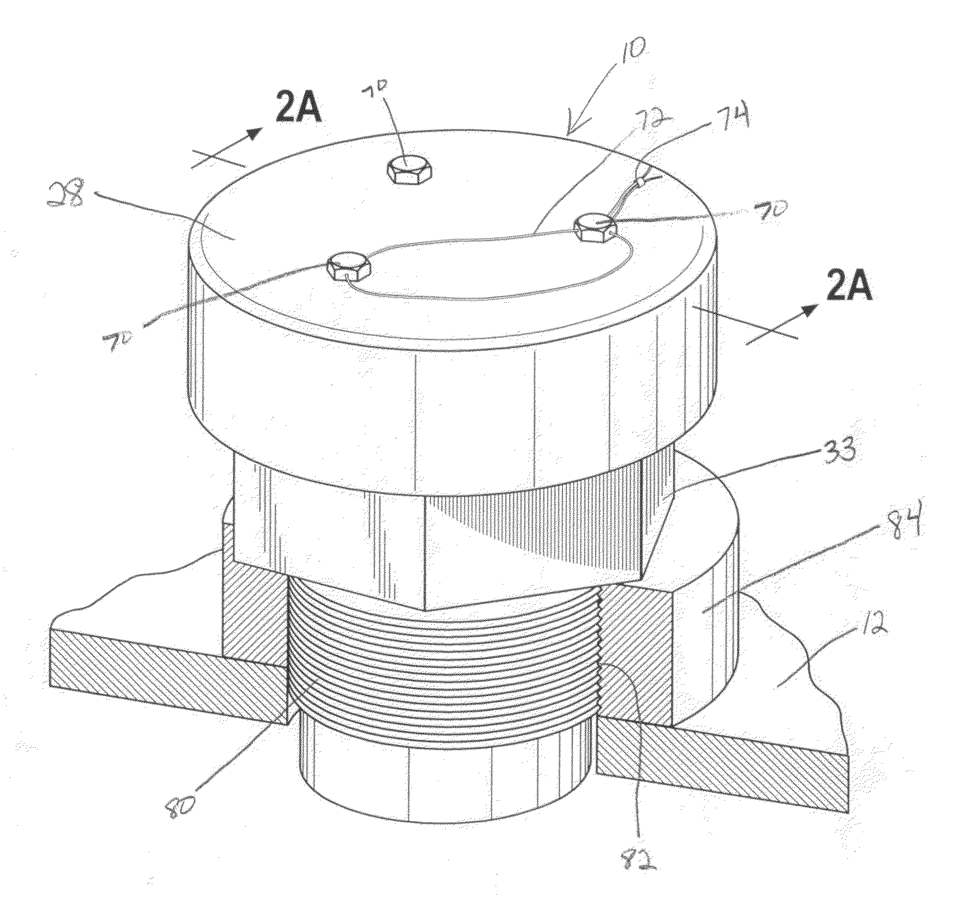
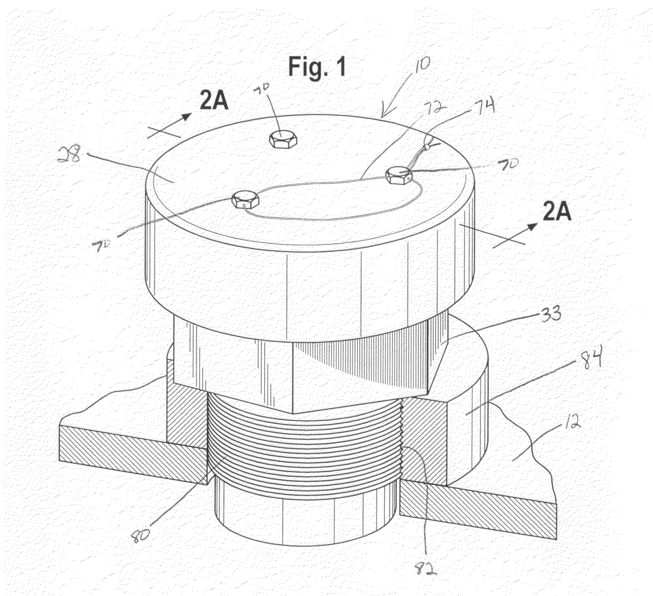
[0025]Referring to FIG. 1, there is illustrated a vacuum relief valve generally designated by the numeral 10. The valve 10 is illustrated as being installed on a vessel 12, such as a railroad car tank, ISO tank, tote tank or other vessel. It should be understood that the valve 10 may be configured to function with any type of vessel or other structure to function as a vacuum relief.

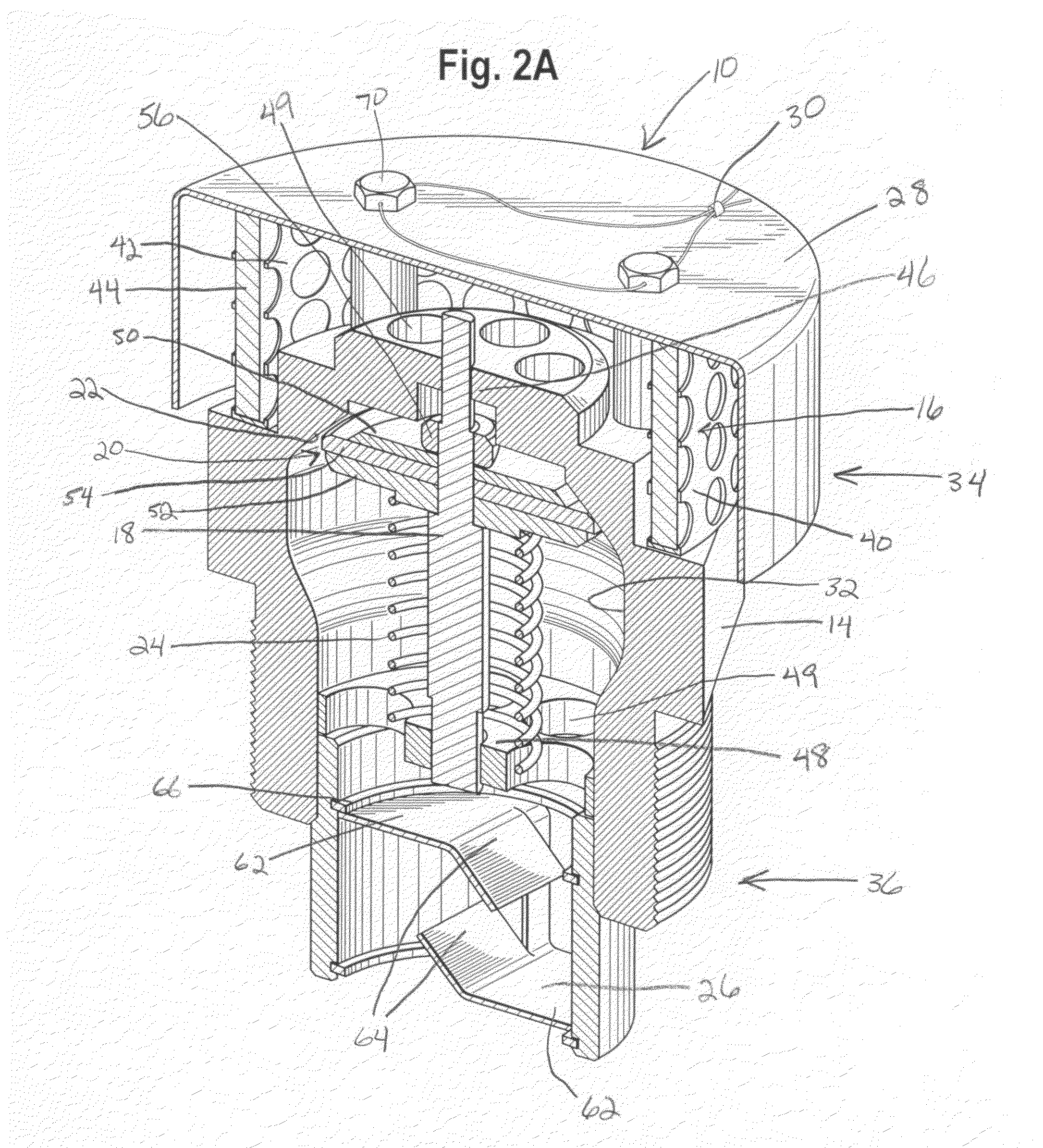
[0026]As shown in FIG. 2A, the valve 10 generally includes a valve body 14, a filter 16, a valve stem 18, a valve seal 20, a valve seat 22 and valve biasing structure 24. The valve 10 may also include a ba...


PUM


Abstract

A vacuum relief valve is provided. The vacuum relief valve includes a valve body, a filter, a valve stem, a valve seal, a valve seat and valve biasing structure. The valve body includes an interior, an inlet side and a tank side. The inlet side is located substantially opposite the tank side. The filter is located at the inlet side. The valve stem is positioned on the interior the valve body. The valve seal is positioned about the valve stem. The valve seat cooperates with the valve seal to seal the vacuum relief valve. The valve biasing structure is located between the valve seal and the tank side. The valve biasing structure is configured to bias the valve seal towards the valve seat.

Description

TECHNICAL FIELD OF THE INVENTION[0001]The present device relates to valves. Particularly, the present device relates to vacuum relief valves, such as used on railroad tank cars and other storage and transport containers.BACKGROUND OF THE INVENTION[0002]Valves and valve systems are used to control pressure within containers and flow into and out of containers. For example, vacuum relief valves are used to control the pressure within a storage vessel such that the negative pressure differential between the storage vessel and the ambient atmosphere is not too large. In this regard, vacuum relief valves permit ambient gas to enter the storage vessel when the pressure within the storage vessel falls below the ambient pressure by a specified amount. The pressure differential can result from a number of factors, including, but not limited to, temperature changes of the vessel or contents, changes in size of the vessel, removal of some or all of the contents of the vessel and other factors....

Claims


Application Information

Patent Timeline
IPC IPC(8): F16K15/00F16K17/00
CPCF16K24/06F16K15/063Y10T137/7897
Inventor JAKUBOWSKI, WILLIAM J.
Owner DELAWARE CAPITAL FORMATION
Why Eureka
Try Eureka