
Resistance welding method

a welding method and resistance technology, applied in welding monitoring devices, welding apparatus, manufacturing tools, etc., can solve problems such as sputtering, and achieve the effect of promoting the growth of nuggets and minimizing the occurrence of sputtering

Inactive Publication Date: 2011-07-28
HONDA MOTOR CO LTD
View PDF13 Cites 26 Cited by
  • Summary
  • Abstract
  • Description
  • Claims
  • Application Information

AI Technical Summary

Benefits of technology

It is an object of the present invention to provide a resistance welding method which minimizes the occurrence of sputtering to promote the growth of a nugget.
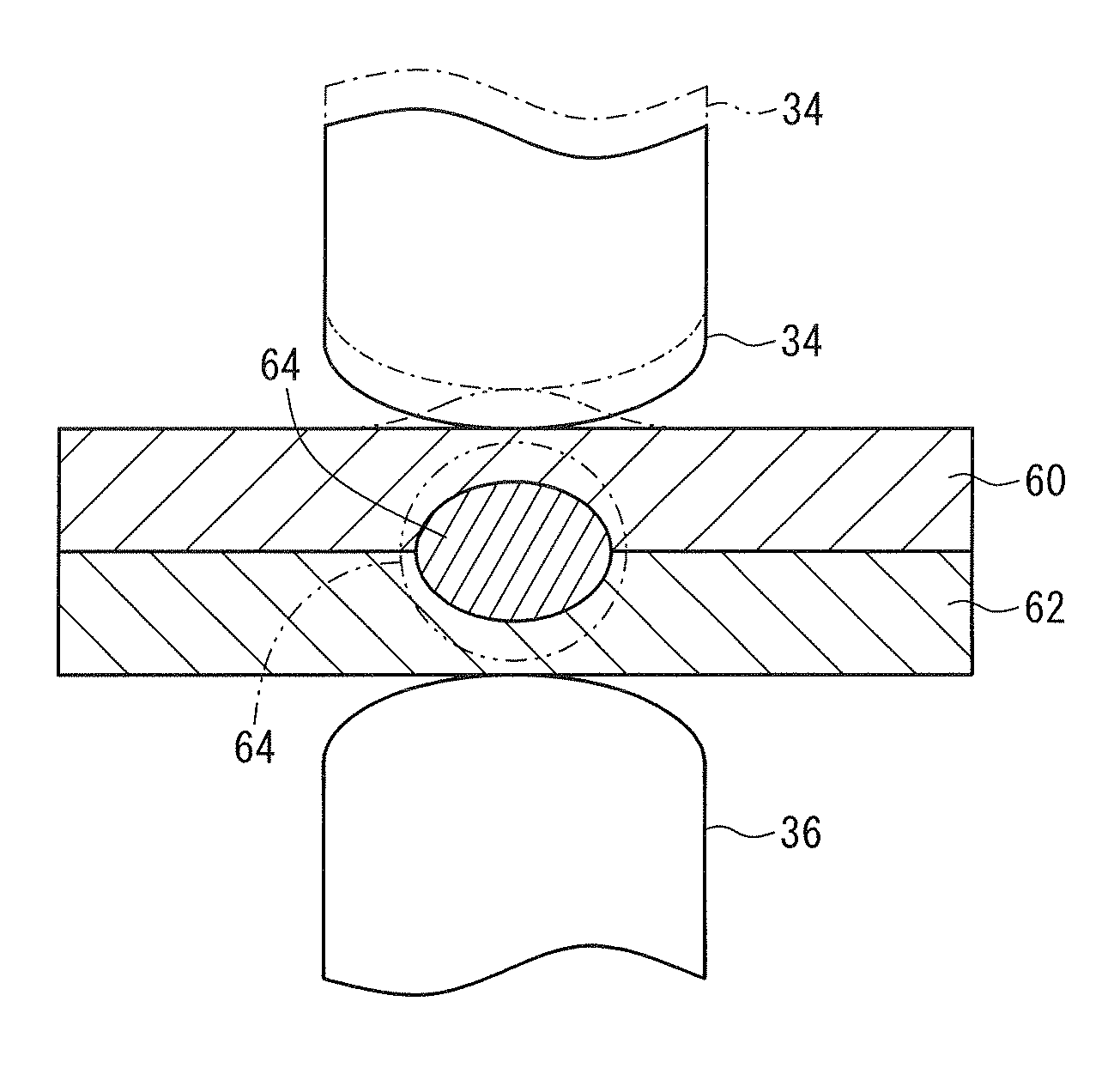
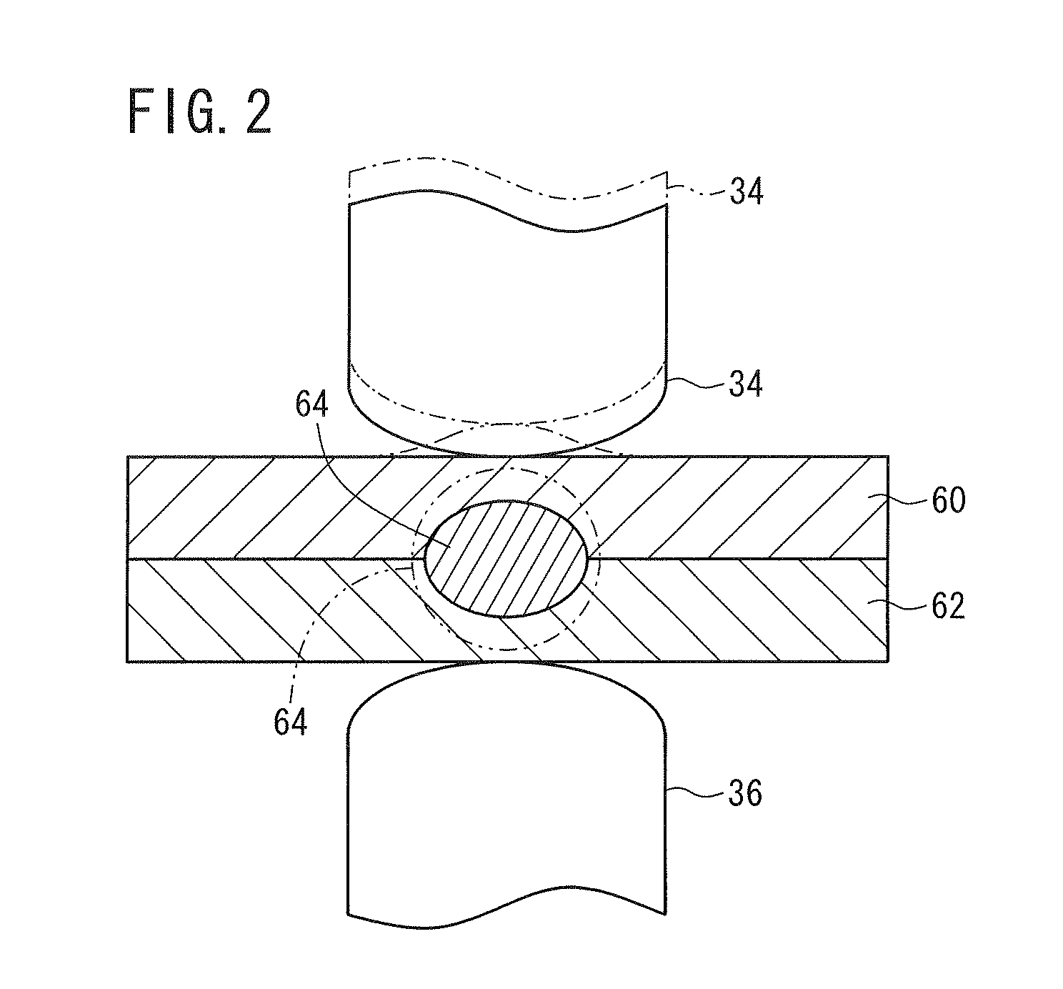
According to the present invention, in a resistance welding process, a change in the amount of expansion of the nugget produced in and between the workpieces is detected along the direction in which the electrode tips grip the workpieces. After the detected change is judged as being smaller than the threshold value, the welding current flowing through the workpieces is gradually increased. Therefore, while the nugget is quickly growing along the direction in which the electrode tips grip the workpieces, the welding current is relatively small to prevent sputtering from developing. While the nugget is not quickly growing, i.e., while an amount of heat generated by the resistance welding process is increasing, the welding current is increased to promote the growth of the nugget, and the time in which the workpieces are resistance-welded, i.e., the welding time, is shortened without significantly causing sputtering.
According to the present invention, furthermore, in a resistance welding process, a change in the amount of expansion of the nugget produced in and between the workpieces is detected along the direction in which the electrode tips grip the workpieces. After the detected change is judged as being smaller than the threshold value, the welding pressure applied to the workpieces is lowered. Therefore, while the nugget is quickly growing along the direction in which the electrode tips grip the workpieces, the workpieces are pressed under a high welding pressure to minimize sputtering. While the nugget is not quickly growing, i.e., while an amount of heat generated by the resistance welding process is increasing, the welding pressure applied to the workpieces is lowered, resulting in an increase in the contact resistance between the workpieces and the electrode tips. Consequently, the growth of the nugget is promoted, reducing the welding time without significantly causing sputtering.

Problems solved by technology

Dependent on the time when the current starts to be progressively increased, sputtering may occur tending to impede the growth of the nugget.

Method used


Image

  • Resistance welding method
  • Resistance welding method
  • Resistance welding method

Examples


Embodiment Construction

A resistance welding method according to a preferred embodiment of the present invention in relation to a resistance welding apparatus which carries out the resistance welding method will be described in detail below with reference to the accompanying drawings.

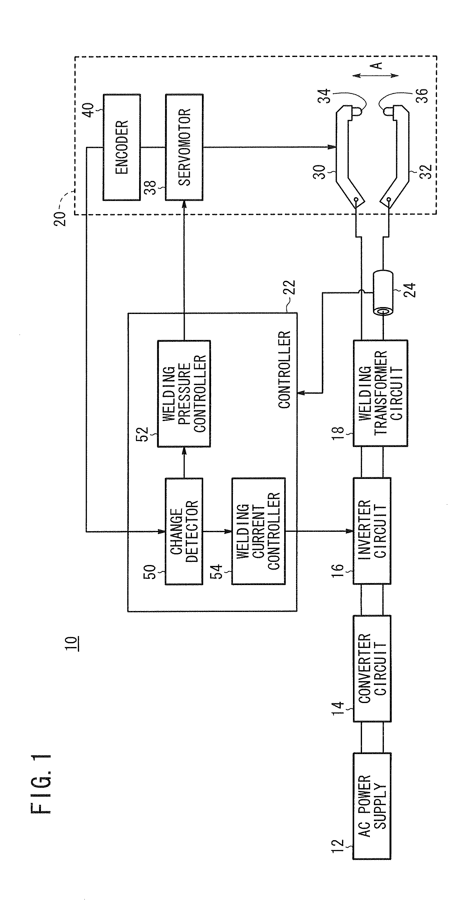
FIG. 1 is a block diagram of a resistance welding apparatus 10 according to an embodiment of the present invention. As shown in FIG. 1, the resistance welding apparatus 10 comprises a converter circuit 14 for converting an alternating current output from an AC power supply 12 into a direct current, an inverter circuit 16 for converting the direct current into a high-frequency alternating current, a welding transformer circuit 18 for transforming and rectifying the high-frequency alternating current, a welding gun assembly 20 for gripping a pair of workpieces, a controller 22 for controlling a welding current which passes through the workpieces and a welding pressure applied to the workpieces, and a current detector 24 for dete...


PUM

PropertyMeasurementUnit
Threshold limitaaaaaaaaaa

Abstract

A resistance welding method, which resistance-welds a pair of workpieces by gripping the workpieces with a pair of electrode tips under a prescribed welding pressure, and supplies a welding current through the electrode tips to the workpieces, includes the steps of detecting a change in an amount of expansion of a nugget produced in the workpieces, along a direction in which the electrode tips grip the workpieces therebetween, determining whether the detected change is smaller than a threshold value or not, and gradually increasing the welding current flowing through the workpieces after the detected change is judged as being smaller than the threshold value.

Description

CROSS-REFERENCE TO RELATED APPLICATIONThis application is based upon and claims the benefit of priority from Japanese Patent Application No. 2010-016095 filed on Jan. 28, 2010, of which the contents are incorporated herein by reference.BACKGROUND OF THE INVENTION1. Field of the InventionThe present invention relates to a resistance welding method for resistance-welding workpieces efficiently by controlling a welding pressure applied to the workpieces and a welding current passing through the workpieces.2. Description of the Related ArtAs disclosed in Japanese Laid-Open Patent Publication No. 04-178274, there has heretofore been known a technical concept about a resistance welding process wherein while electrode tips held in contact with workpieces to be welded are being energized, a high current is initially supplied to the workpieces, and then a reduced current is supplied to the workpieces at the time a nugget starts to be formed in the workpieces, followed by a progressively incr...

Claims


Application Information

Patent Timeline
IPC IPC(8): B23K11/25B23K11/00
CPCB23K11/253B23K11/115
Inventor HASEGAWA, EISAKUAOKI, YUSHIKANEKO, MITSUGUMAKITA, TAKUTAKEISHI, KATSUMI
Owner HONDA MOTOR CO LTD
Learn More