Stator for use in electric rotating machine

Active Publication Date: 2011-07-28
DENSO CORP
View PDF5 Cites 15 Cited by
  • Summary
  • Abstract
  • Description
  • Claims
  • Application Information

AI Technical Summary

Benefits of technology

[0008]It is another object of the invention to provide a stator for use in an electric rotating machine which ensures the stability in electric insulation of a stator winding.
[0010]The formation of the pattern of texture on each of the joints results in an increased area of the surface of the joint to which the insulating coating is adhered and entry of the insulating coating deep into recesses in the surface of the joint, which leads to an increased degree of adhesion of the insulating coating to the joint. This improves the adhesion of the insulating coatings to joints against hits of cooling air contacting dust or numerous impurities on the surface of the insulating coatings on the joints and ensures the stability in insulating the joints electrically.

Problems solved by technology

The hits of the cooling air on the joints may result in physical damages to the insulating coating on the joints.
The hits of the cooling air or the impurities on the joints may, therefore, result in removal of the insulating coating from the joints, which leads to a failure in insulation between the joints themselves or between the joints and the peripheral member.

Method used


Image

  • Stator for use in electric rotating machine
  • Stator for use in electric rotating machine
  • Stator for use in electric rotating machine

Examples


Embodiment Construction

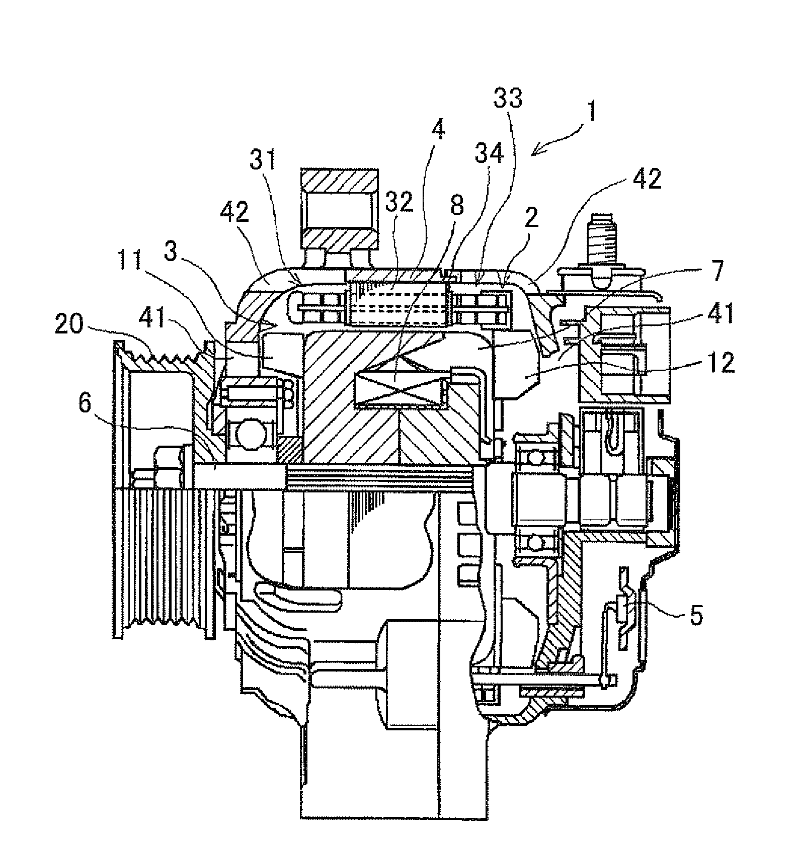
[0031]Referring to the drawings, wherein like reference numbers refer to like parts in several views, particularly to FIG. 1, there is shown an electric rotating machine 1 according to an embodiment of the invention. The electric rotating machine 1, as referred to herein, is used as an AC generator to be mounted in an automotive vehicle.

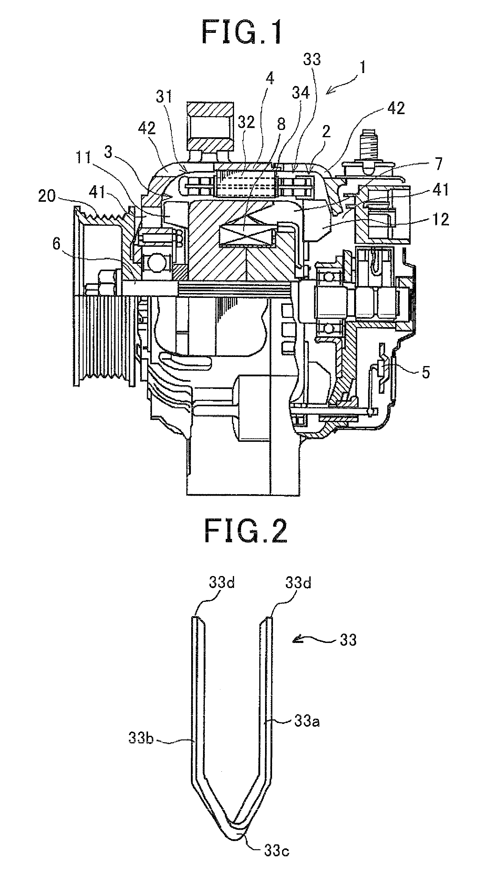
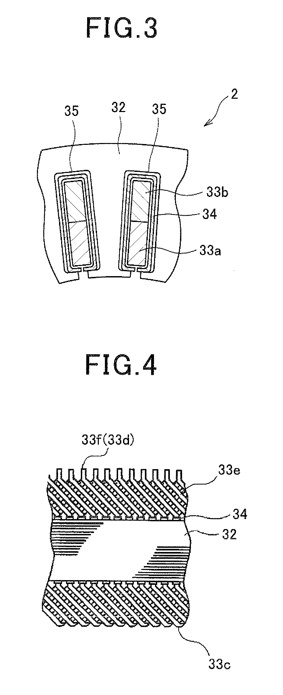
[0032]The AC generator 1 includes a stator 2, a rotor 3, a frame 4, and a rectifier 5. The stator 2 is equipped with a stator core 32, a plurality of conductor segments (also called electric wire segments) 33, and an insulator 34. The conductor segments 33 make up a stator winding. The insulator 34 insulates the stator core 32 and the conductor segments 33 electrically from each other. The stator core 32 is made of a stack of annular steel plates and has a plurality of slots 35 formed therein. The slots 35 extend through the stator core 32 in an axial direction thereof and are arrayed in a circumferential direction of the stator core 32. The slots 35...


PUM


Abstract

A stator for use in an electric rotating machine is provided which includes a stator winding wound through slots of a stator core. The stator winding is made up of a plurality of conductor segments connected together. Each of the conductor segments includes an in-slot portion disposed inside one of the slots and out-slot portions extending from the in-slot portion outside at least one of the ends of the stator core. Ends of the out-slot portions are joined together to form the stator winding. The joints of the ends of the out-slot portions have a given pattern of texture formed on surfaces thereof and coated with an insulating material. The pattern of texture enhances the adhesion of the insulating coatings to the surfaces of the joints and ensures the stability in electric insulation of the joints.

Description

CROSS REFERENCE TO RELATED DOCUMENT[0001]The present application claims the benefit of priority of Japanese Patent Application No. 2010-11686 filed on Jan. 22, 2010, the disclosure of which is incorporated herein by reference.BACKGROUND OF THE INVENTION[0002]1. Technical Field of the Invention[0003]The present invention relates generally to a stator which may be installed in a motor-generator or an AC generator for use in automotive vehicles such as electric vehicles or hybrid vehicles.[0004]2. Background Art[0005]Japanese Patent First Publication No. 11-341730 discloses a stator of an electric rotating machine. The stator is equipped with a stator core facing a rotor and a stator winding wound in the stator core. The stator core has a plurality of slots formed therein. The stator winding is made up of a plurality of conductor segments each of which includes in-slot portions disposed within the slots of the stator core and coil end portions extending from the slot outside either of ...

Claims


Application Information

Patent Timeline
IPC IPC(8): H02K3/00
CPCH02K15/0081H02K3/38
Inventor HASEGAWA, SYOMORIGUCHI, KEIGOTAKEDA, HIROAKI
Owner DENSO CORP
Why Eureka
Try Eureka