Method and device for ascertaining the rotor temperature of a permanent-magnet synchronous machine

a technology of permanent magnet synchronization and rotor temperature, which is applied in the direction of motor/generator/converter stopper, dynamo-electric converter control, instruments, etc., can solve the problems of loss of magnetization, damage to magnets, and technical complexity of monitoring the rotor temperature, so as to achieve the effect of increasing precision

Active Publication Date: 2011-07-28
ROBERT BOSCH GMBH
View PDF8 Cites 23 Cited by
  • Summary
  • Abstract
  • Description
  • Claims
  • Application Information

AI Technical Summary

Benefits of technology

[0007]Accordingly, the object of the present invention is to improve upon a method and a device of the type defined in the introduction, to the effect that increased precision is achieved in ascertaining the rotor temperature.
[0008]This object is achieved in a method of the type defined above according to the present invention by ascertaining a second estimate for the rotor temperature via a Kalman filter containing a thermal model of the synchronous machine, the first estimate for the rotor temperature being supplied at least intermittently to this Kalman filter. In other words, according to the present invention, in addition to the first estimate, which is known from the traditional methods, a second estimate is also ascertained. The use of the thermal model of the synchronous machine allows a particularly advantageous estimate of the rotor temperature here based on input variables, which are detectable by measurement with little complexity, e.g., the stator temperature. An increased precision in ascertaining the rotor temperature is advantageously achieved through the combination of the conventional first estimate with the Kalman filter containing the thermal model according to the present invention.
[0010]In an advantageous specific embodiment of the method according to the present invention, a particularly simple evaluation of the Kalman filter from the mathematical standpoint is obtained when either only the first estimate for the rotor temperature or the measured value for the stator temperature is supplied to the Kalman filter, in particular for a correction step. It is therefore advantageously possible to omit a matrix inversion of the 2×2 output matrix or measurement matrix in ascertaining the Kalman gain as part of the correction step of the Kalman filter.
[0011]The exclusive evaluation of just one of the two variables within one iteration of the Kalman filter proposed according to the present invention advantageously makes it possible to use a simpler output matrix, so that instead of a matrix inversion, a division by a scalar quantity is possible.
[0014]According to the present invention, it is also possible to use thermal conductance values among the components of the thermal model as a function of a rotational speed of the synchronous machine to increase precision.

Problems solved by technology

In permanent-magnet synchronous machines, the permanent magnets of the rotor are usually the components most sensitive to temperature because if the temperature even briefly exceeds the Curie temperature of the magnetic material used, it will cause damage to the magnets, in particular loss of their magnetization.
Monitoring of the rotor temperature is technically complex due to the rotor movement.
The known method has the disadvantage that the rotor temperature is ascertained on the basis of a linear model, which is valid only in a restricted operating range of the synchronous machine due to magnetic saturation effects, among other things, and offers inadequate precision for many applications.

Method used


Image

  • Method and device for ascertaining the rotor temperature of a permanent-magnet synchronous machine
  • Method and device for ascertaining the rotor temperature of a permanent-magnet synchronous machine
  • Method and device for ascertaining the rotor temperature of a permanent-magnet synchronous machine

Examples


Embodiment Construction

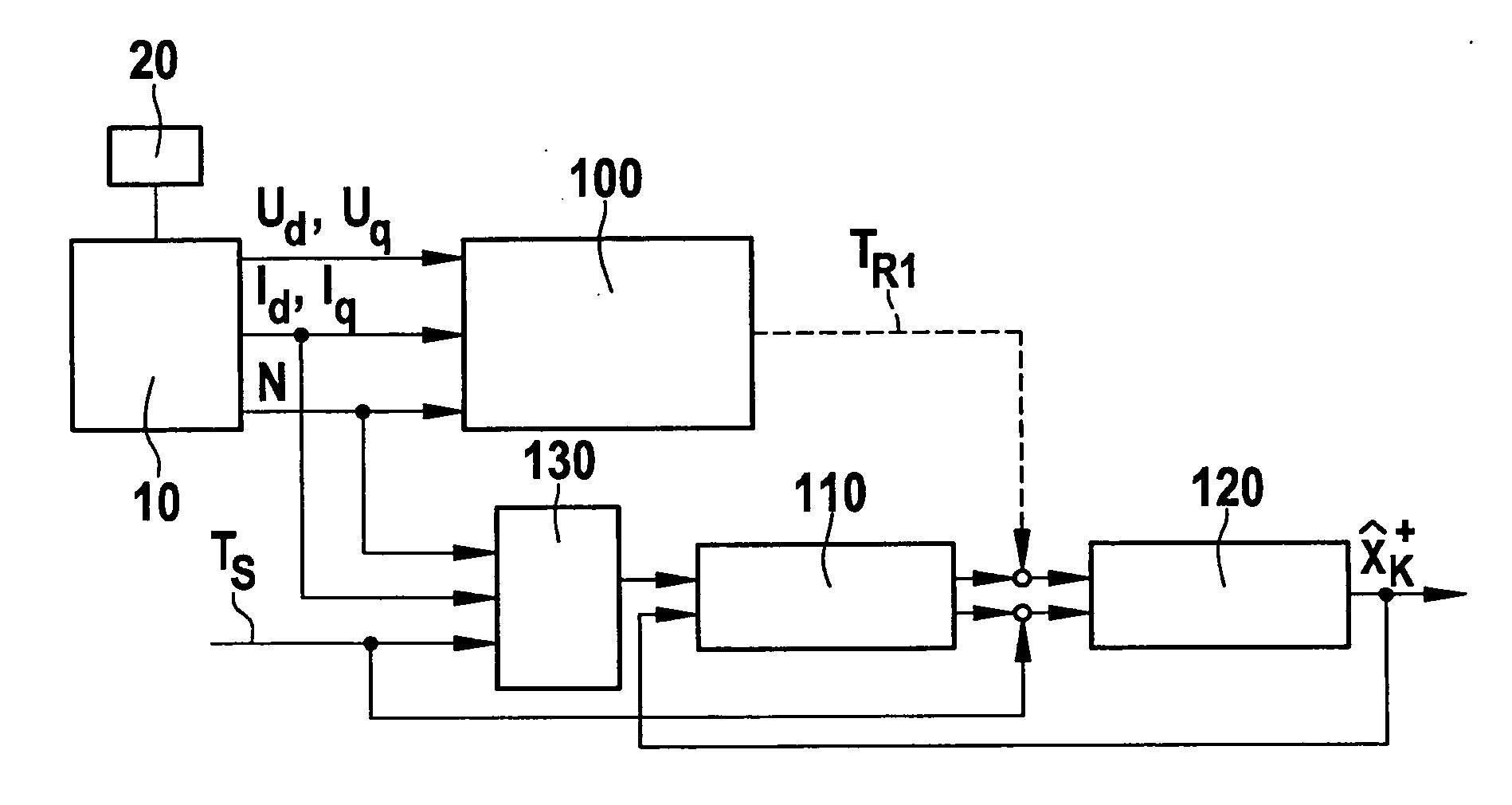
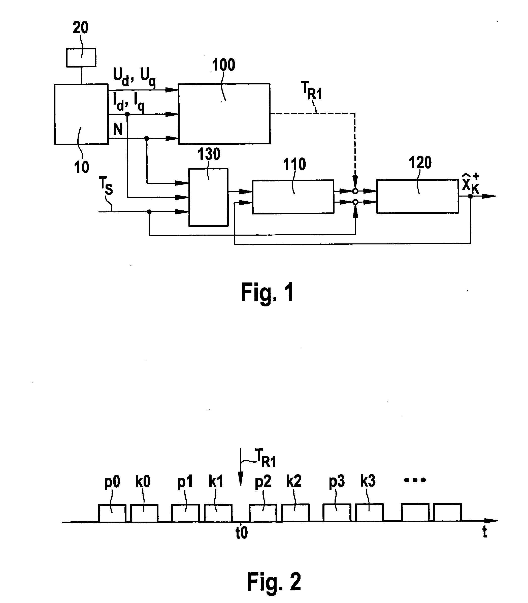
[0019]FIG. 1 schematically shows a permanent-magnet synchronous machine 10, which is controlled by a control unit 20 assigned to it. Electrical operating variables Ud, Uq, Id, Iq and rotational speed N of synchronous machine 10 are sent to an estimator unit 100, which uses them to calculate a first estimate TR1 for the rotor temperature of synchronous machine 10.

[0020]Operating variables Ud, Uq correspond to the voltage of synchronous machine 10 in the d direction and q direction, respectively, and operating variables Id, Iq correspond to the current of synchronous machine 10 in the d direction and q direction, respectively.

[0021]The operating principle of estimator unit 100 is based on the temperature dependence of the remanent flux density of the permanent magnets of the rotor of synchronous machine 10. Since the amplitude of the synchronous internal voltage of synchronous machine 10 is also a function of the rotor temperature, estimator unit 100 may form a first estimate TR1 for ...


PUM


Abstract

A method for ascertaining the rotor temperature of a permanent-magnet synchronous machine (10), in which a first estimate (TR1) for the rotor temperature is ascertained as a function of a remanent flux density of permanent magnets contained in a rotor of the synchronous machine (10). A second estimate (TR2) for the rotor temperature is ascertained via a Kalman filter containing a thermal model of the synchronous machine (10), the first estimate (TR1) for the rotor temperature being supplied at least intermittently to the Kalman filter.

Description

BACKGROUND OF THE INVENTION[0001]1. Field of the Invention[0002]The present invention relates to a method and a device for ascertaining the rotor temperature of a permanent-magnet synchronous machine, in which a first estimate of the rotor temperature is ascertained as a function of a remanent flux density of permanent magnets contained in a rotor of the synchronous machine.[0003]2. Description of the Related Art[0004]In permanent-magnet synchronous machines, the permanent magnets of the rotor are usually the components most sensitive to temperature because if the temperature even briefly exceeds the Curie temperature of the magnetic material used, it will cause damage to the magnets, in particular loss of their magnetization. Therefore, temperature monitoring of the rotor of the synchronous machine is advisable to protect the permanent magnets, so that the synchronous machine may be deactivated, e.g., shortly before reaching the Curie temperature.[0005]Monitoring of the rotor tempe...

Claims


Application Information

Patent Timeline
Patent Type & Authority Applications(United States)
IPC IPC(8): H02P23/14
CPCG01K7/42H02P29/0066H02P29/0044G01K2205/00H02P29/60H02P29/662
Inventor VOLLMER, ULRICHBITZER, MATTHIAS
Owner ROBERT BOSCH GMBH
Why Eureka
Try Eureka