Liquid jetting head unit and image forming apparatus
a liquid jetting head and image forming technology, applied in the direction of inking apparatus, separation process, filtration separation, etc., can solve the problems of ink jetting failure, droplet jetting direction change, droplet jetting failure,
- Summary
- Abstract
- Description
- Claims
- Application Information
AI Technical Summary
Benefits of technology
Problems solved by technology
Method used
Image

Examples
first embodiment
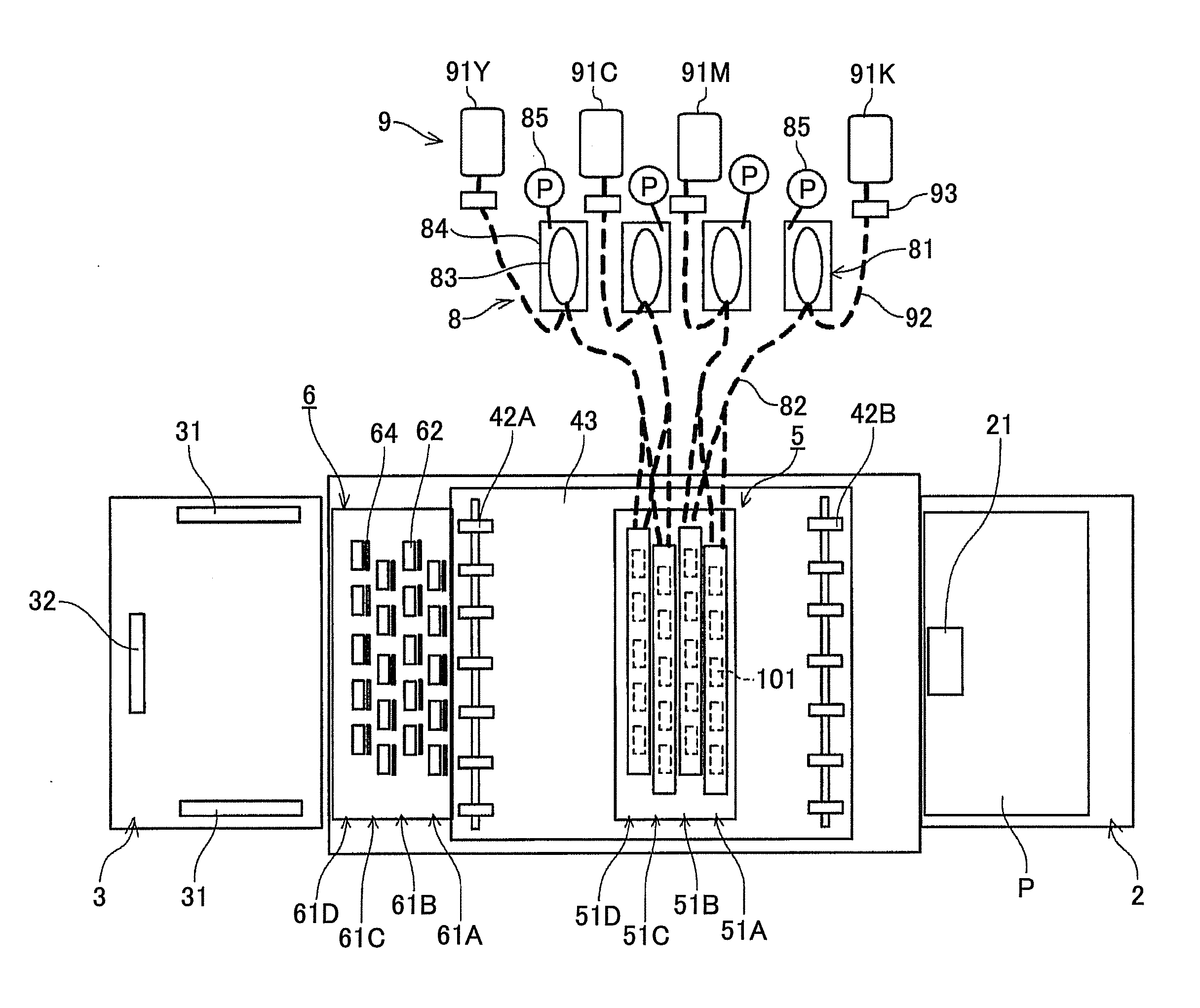
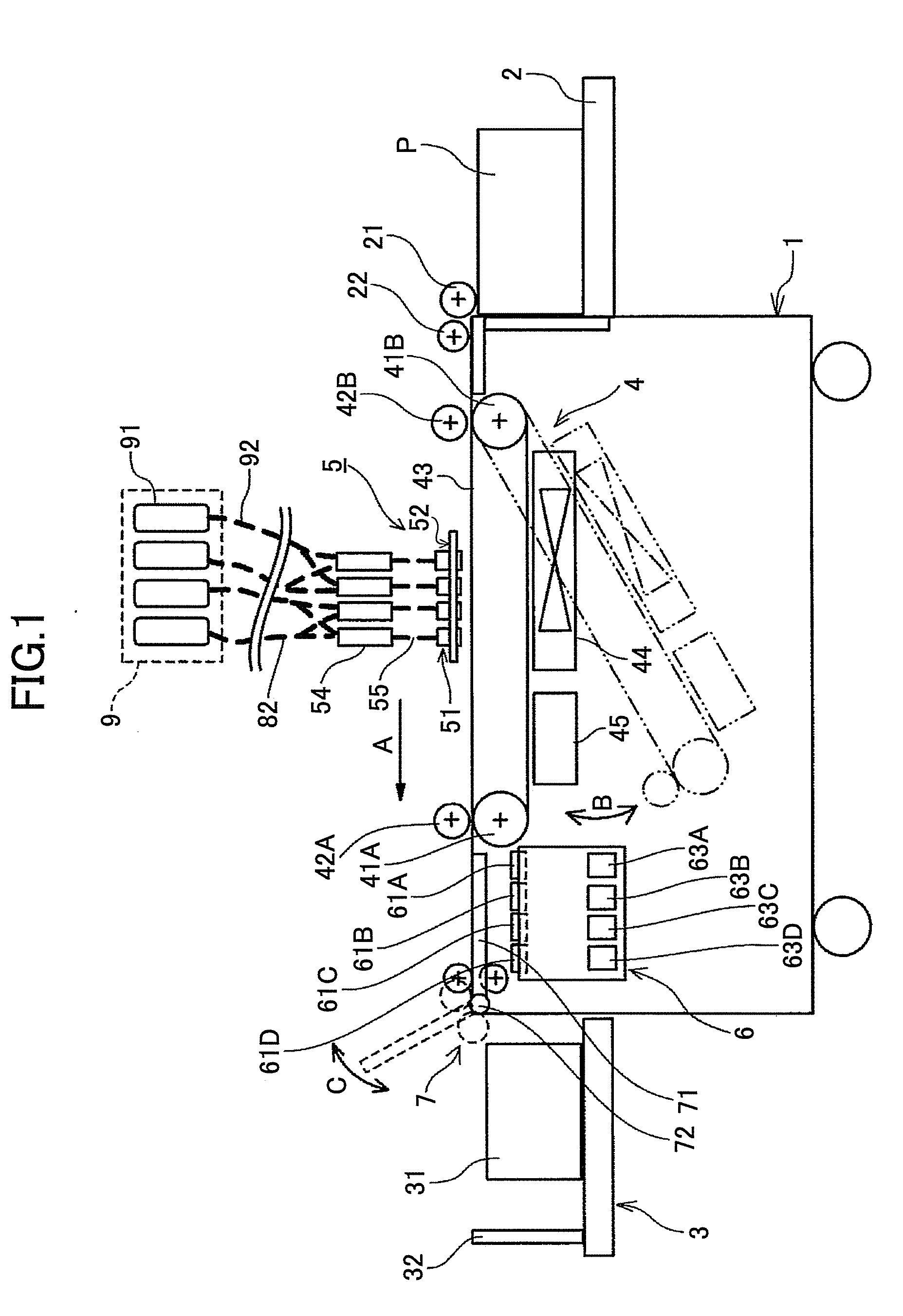
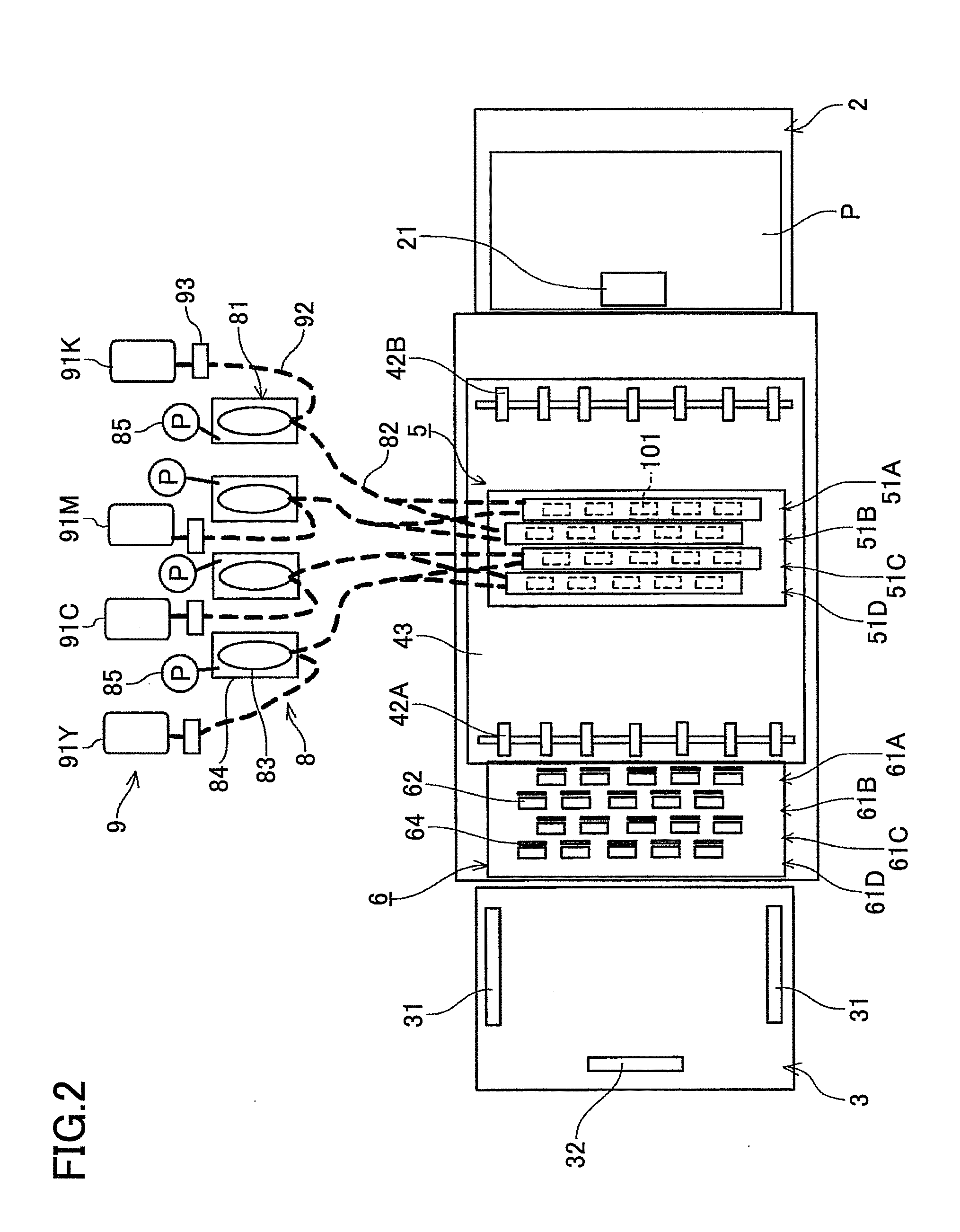
[0059]Next, a detailed description is given of the head unit 101 according to the present invention with reference to FIG. 5. FIG. 5 is a schematic cross-sectional view of the head unit 101.
[0060]The head unit 101 includes the head 201 for jetting liquid droplets and the head tank 202 which is a liquid storing tank according to an embodiment of the present invention for storing ink to be supplied to the head 201. The head 201 and the head tank 202 are integrally combined.
[0061]The head 201 includes plural nozzles 211 for jetting liquid droplets, liquid chambers 212 connected to the nozzles, a common liquid chamber (common flow path) 213 connected to the liquid chambers 212, an ink supply port 214 through which ink is supplied into the common liquid chamber 213, and an ink discharge port 215 through which ink is discharged from the common liquid chamber 213.
[0062]The head tank 202 is provided with a storing unit 223 for storing ink supplied into a tank case (tank main unit) 221. The ...
second embodiment
[0077]In the present embodiment, a check valve (impurity flow-in preventing unit) 235 is provided instead of the filter member 234 in the discharge path 228 of the The check valve 235 allows the ink to flow in the discharging direction so that the ink is prevented from flowing in the opposite direction.
[0078]According to the above configuration, in a regular jetting operation, the ink, which flows from the filter upstream chamber 223A to the discharge path 228 through the second connection path 232 (ink that has not passed through the filter member 224), is prevented from flowing toward the head 201 through the discharge path 228.
[0079]A first example of the check valve 235 is described with reference to FIGS. 10A and 10B. FIGS. 10A and 10B schematically illustrate the check valve 235.
[0080]The check valve 235 includes a valve seat 241 provided inside the discharge path 228, a ball 242, and a spring 243 that biases the ball 242 toward the valve seat 241.
[0081]During the circulation...
PUM
| Property | Measurement | Unit |
|---|---|---|
| Electrical resistance | aaaaa | aaaaa |
Abstract
Description
Claims
Application Information
 - R&D
- Intellectual Property
- Life Sciences
- Materials
- Tech Scout
- Unparalleled Data Quality
- Higher Quality Content
- 60% Fewer Hallucinations
Browse by: Latest US Patents, China's latest patents, Technical Efficacy Thesaurus, Application Domain, Technology Topic, Popular Technical Reports.
© 2025 PatSnap. All rights reserved.Legal|Privacy policy|Modern Slavery Act Transparency Statement|Sitemap|About US| Contact US: help@patsnap.com