Adjusting device for variable guide vanes and method of operation

Active Publication Date: 2011-07-28
SIEMENS ENERGY GLOBAL GMBH & CO KG
View PDF7 Cites 27 Cited by
  • Summary
  • Abstract
  • Description
  • Claims
  • Application Information

AI Technical Summary

Benefits of technology

[0020]In a preferred embodiment the disproportionate longitudinal movement of the first end of the at least one lever resulting in a disproportionate rotation of the respective adjusting ring.
[0021]In a further preferred embodiment a single driving ram—preferably via a bell crank which is located in between the driving ram and the plurality of levers—may be attached to a second end of the plurality of levers.

Problems solved by technology

In some cases it may not be ideal to have a proportional system.

Method used


Image

  • Adjusting device for variable guide vanes and method of operation
  • Adjusting device for variable guide vanes and method of operation
  • Adjusting device for variable guide vanes and method of operation

Examples


Embodiment Construction

[0046]Some of the features and especially the advantages will be explained for an assembled gas turbine, but obviously the features can be applied also to the single components of the gas turbine but may show the advantages only once assembled and during operation. But when explained by means of a gas turbine during operation none of the details should be limited to a gas turbine while in operation.

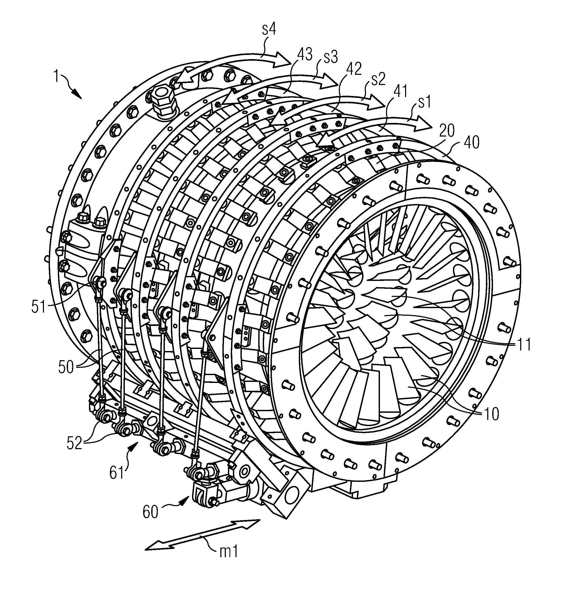
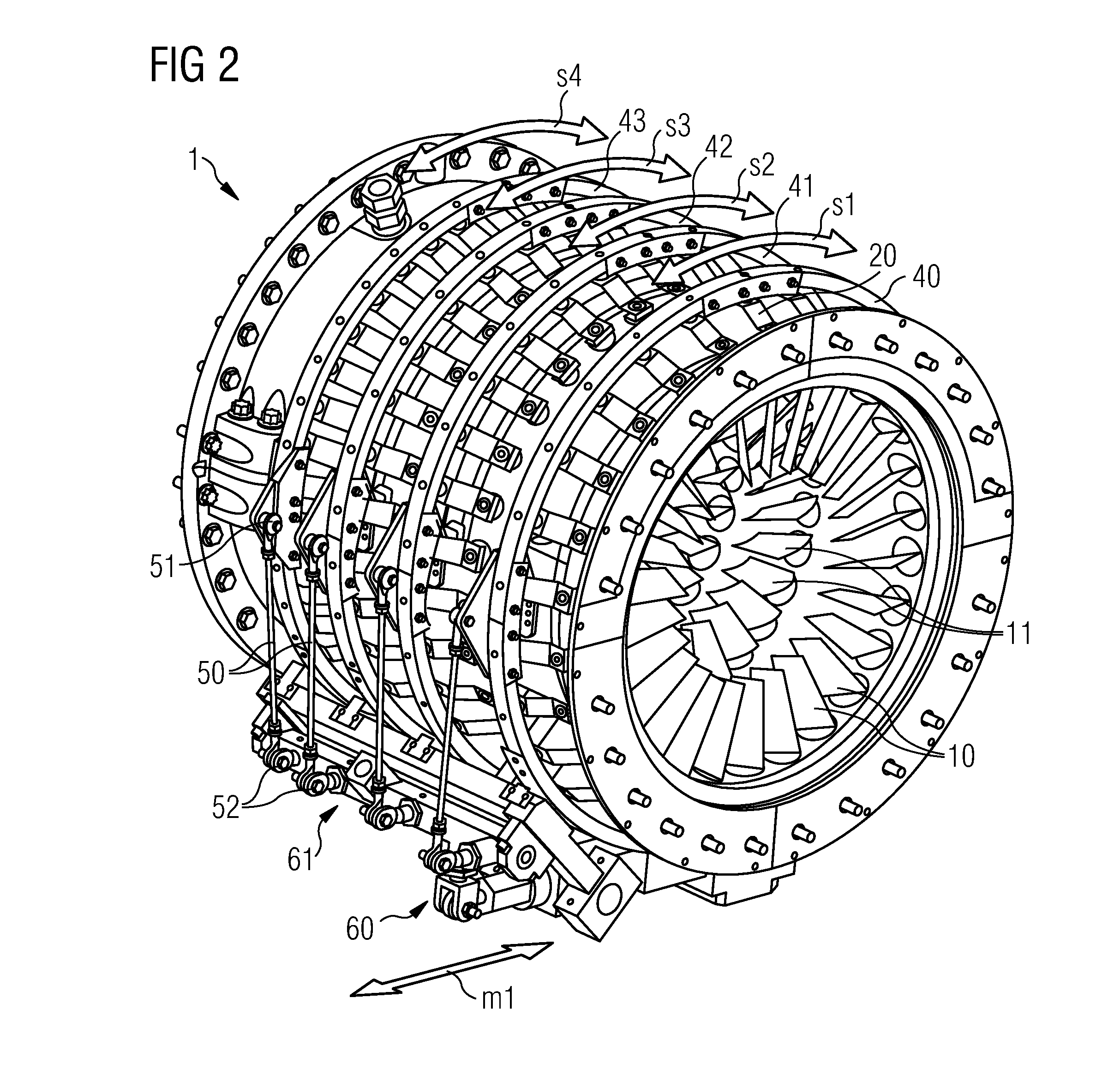
[0047]The invention may be applied to a gas turbine engine that can generally include a compressor section 1 (see FIG. 2), a combustor section (not shown) and a turbine section (not shown). A centrally disposed rotor (not shown) can extend through these three sections. The compressor section 1 can include alternating rows of vanes 10, 11, . . . and rotating blades (not shown).

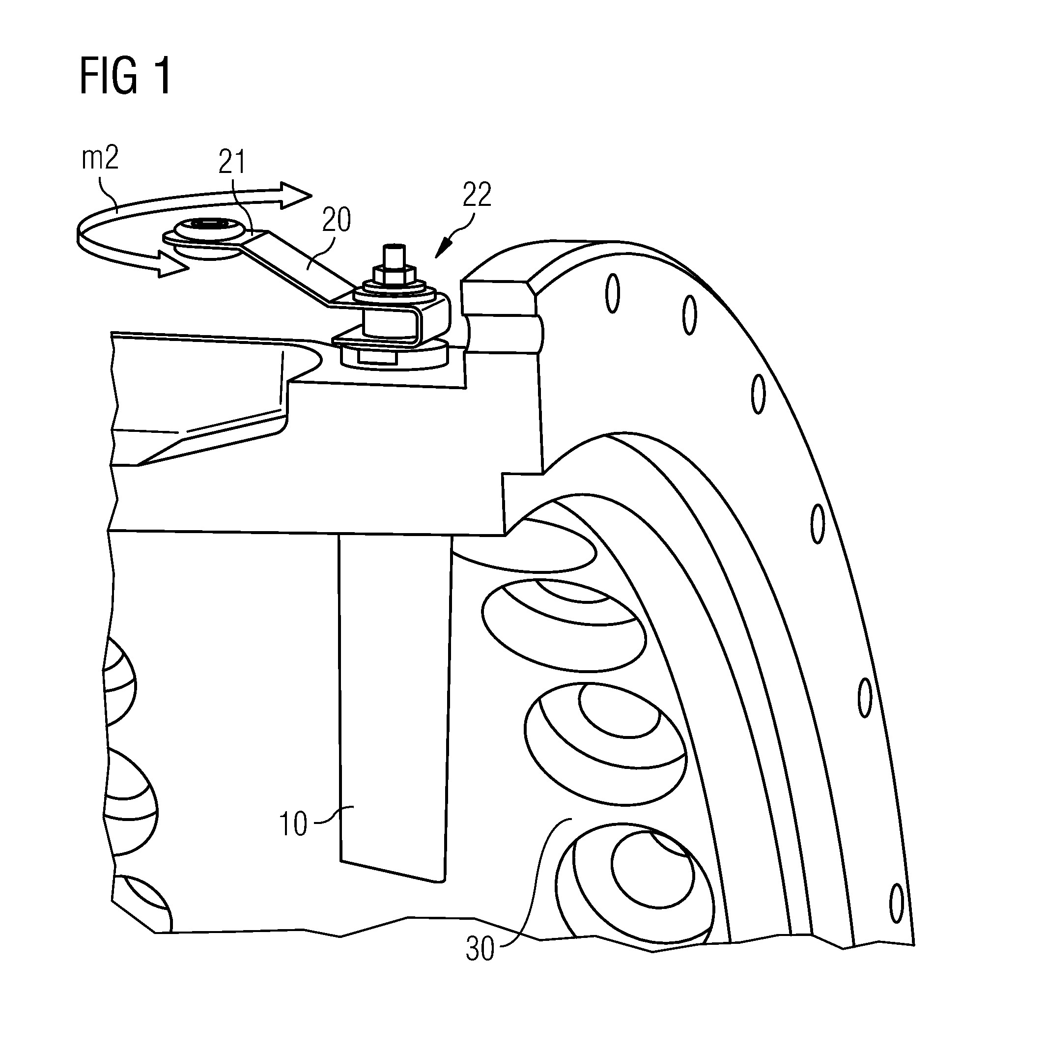
[0048]The invention is directed to a compressor with “Variable Guide Vanes” (VGV). This is a construction with variable pitch of the stator vanes 10, 11, . . .

[0049]Based on FIGS. 1, 2, 3, and 4 the general concept o...


PUM


Abstract

A device, system, or method to position variable guide vanes disproportionately is provided. An adjusting device for guide vanes of an axial-flow machine, includes a plurality of rotatably mounted rings of variable guide vanes, a plurality of levers which are arranged on the outer sides of a guide vane carrier for rotating the variable guide vanes, a plurality of adjusting rings, each of the adjustment rings is arranged coaxially to the guide vane carrier and to which a first end of one of the levers is connected, and an adjusting drive with which the adjusting rings may be moved in the peripheral direction. At least one of the levers is set up to perform at least partly a disproportionate longitudinal movement of the first end of the at least one lever.

Description

CROSS REFERENCE TO RELATED APPLICATIONS[0001]This application is the US National Stage of International Application No. PCT / EP2009 / 061953, filed Sep. 15, 2009 and claims the benefit thereof. The International Application claims the benefits of European Patent Office application No. 08016490.8 EP filed Sep. 18, 2008. All of the applications are incorporated by reference herein in their entirety.FIELD OF INVENTION[0002]The invention relates to a method, system, device for variable guide vanes.BACKGROUND OF INVENTION[0003]A gas turbine comprises a turbine and a compressor driven by the turbine. In particular, when the gas turbine is provided for a gas-steam power plant, the compressor is of the axial flow type. Commonly, the gas turbine is subjected to varying operating conditions resulting in different aerodynamic flow conditions within the compressor. In order to adapt the compressor performance to different operating demands, it is known to provide the compressor with variable guide...

Claims


Application Information

Patent Timeline
IPC IPC(8): F04D29/56
CPCF01D17/162F05D2260/79F01D17/20F04D17/122F04D29/563
Inventor LEITHEAD, GRAEMESMITH, MICHAELTWELL, PHILIP
Owner SIEMENS ENERGY GLOBAL GMBH & CO KG
Why Eureka
Try Eureka