Motor vehicle door lock

a technology for motor vehicles and door locks, applied in the direction of building locks, fastening means, construction, etc., can solve the problems of insatiable functionality, complex and costly design of closing/opening devices, etc., and achieve the effect of simple and cost-effective design and significant reduction of required operating forces

Active Publication Date: 2011-08-04
KIEKERT AG
View PDF9 Cites 21 Cited by
  • Summary
  • Abstract
  • Description
  • Claims
  • Application Information

AI Technical Summary

Benefits of technology

[0006]The invention is based on the technical problem of further developing a motor vehicle door lock of the type described above in such a way that, whilst providing a simple and cost-effective design, the required operating forces are significantly reduced, in particular when interrupting the closing movement.
[0010]To achieve this, the triggering lever or ejecting lever acts on the lever actuating mechanism in such a way that it is moved from its engaged state into its disengaged state. Simultaneously with moving into the disengaged state, the locking mechanism is released, where applicable. In this way a closing movement of the closing / opening device of the invention can, for instance, be interrupted at any time without problem and with little force and can, in the example, open the respective motor vehicle door. To achieve this, an operator would only have to apply a force with the aid of the lock actuating lever onto the triggering lever or ejecting lever, which in turn moves the lever actuating mechanism from its engaged state into its disengaged state. This requires only a minimum force and provides a responsive action. So if, for instance, a child jams its hand in the motor vehicle door when closing the door, the child's operating force will suffice to directly disengage the lever actuating mechanism and to release the locking mechanism or, in any case, to stop the closing process.
[0011]As a result, the closing operation is immediately interrupted and the respective motor vehicle door can, due to the released locking mechanism, be easily opened from either the inside or the outside—if the unit is first disengaged. With the aid of the lock actuating lever the lever actuating mechanism can be interrupted to open the locking mechanism from the inside and from the outside. This is possible, as the lock actuating lever is an internal operating lever and / or the external operating lever or a main actuating lever, acted upon by the internal operating lever and the external operating lever. The internal operating lever is usually mechanically connected to an internal door handle, whilst the external door handle acts on the external operating lever.
[0018]To achieve this, the driving pawl also and advantageously contains a so-called pre-cut. This means that according to a preferred embodiment, the lever actuating mechanism contains a pre-cut in the area of its contact surface with the locking mechanism. In this way, the locking mechanism, which is acted upon by a spring in the “open” direction, is able to directly eject the disengaged lever actuating mechanism. This means that the pre-cut in the driving pawl of the lever actuating mechanism supports the ejecting movement of the driving pawl, as soon as it is no longer held in position by the latching pawl. This is the case immediately after the triggering lever or ejecting lever acts upon the latching pawl. As a result of this quasi-automatic operation and the use of the already present force of the spring of the locking mechanism for the assumption of the disengaged state of the lever actuating mechanism, the operating force on the lock actuating lever is significantly reduced.
[0019]It has proven to be advantageous for the actuating lever or the operating element for opening the locking mechanism to be designed as a single-arm lever mounted at one end and being angled, where necessary. As a result, the drive provided on the cam can easily act upon said actuating lever at its free end. In most cases, the respective actuating lever is arranged on the same axis as the rotary latch of the locking mechanism, resulting in a particularly compact and cost-effective arrangement. This arrangement also ensures that the drive with the cam can be located directly above the locking mechanism or the rotary latch and that it can consequently also be used in very narrow motor vehicle door locks.

Problems solved by technology

Because of the additional mechanical requirements and thus associated costs, such closing devices or closing aids are at present predominantly reserved for expensive and exclusive cars.
The result is a complex and costly design of the closing / opening device consisting of the drive and the lever actuating mechanism.
The functionality is also not always satisfactory, as considerable operating forces are required to interrupt the closing movement.

Method used


Image

  • Motor vehicle door lock
  • Motor vehicle door lock
  • Motor vehicle door lock

Examples


Embodiment Construction

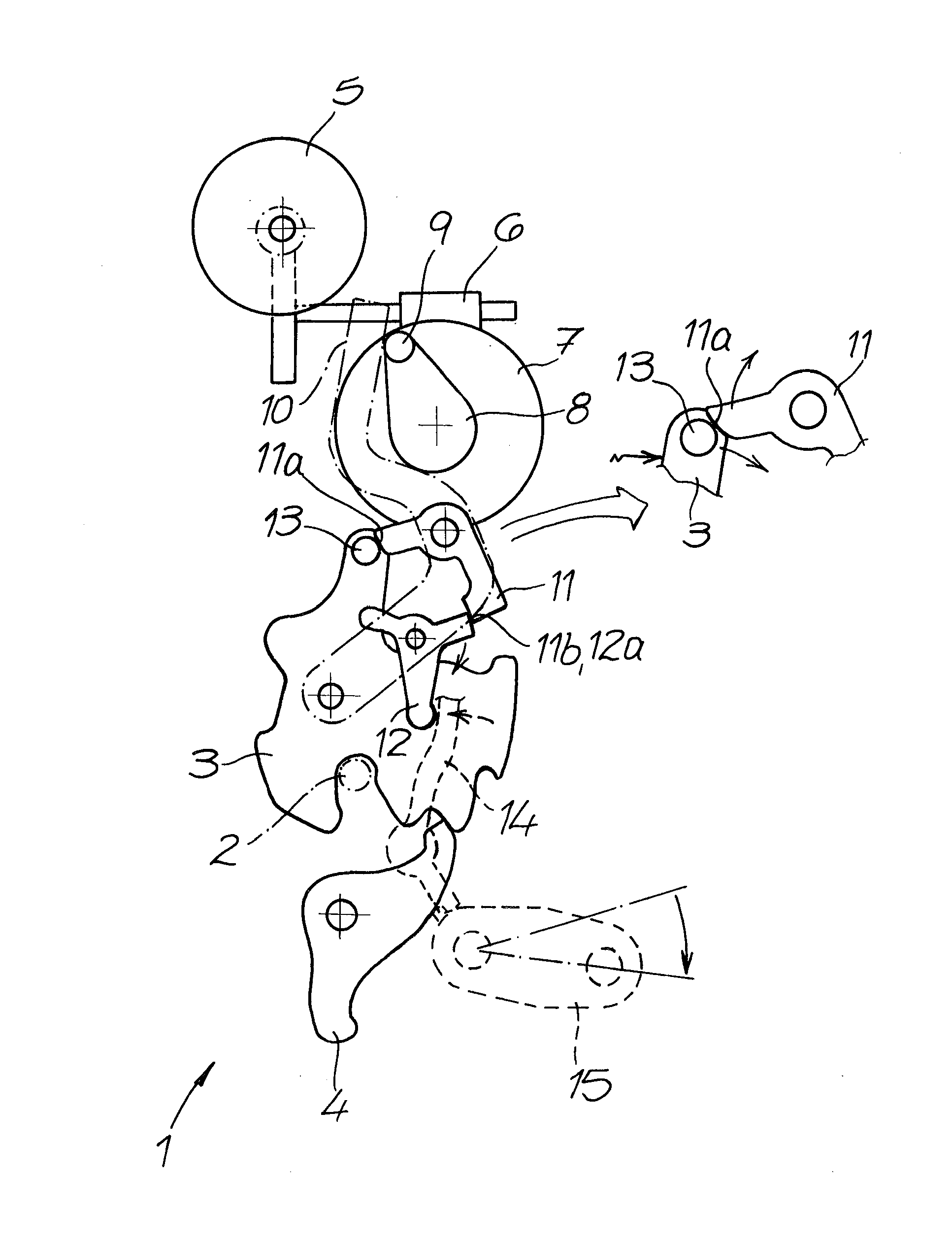
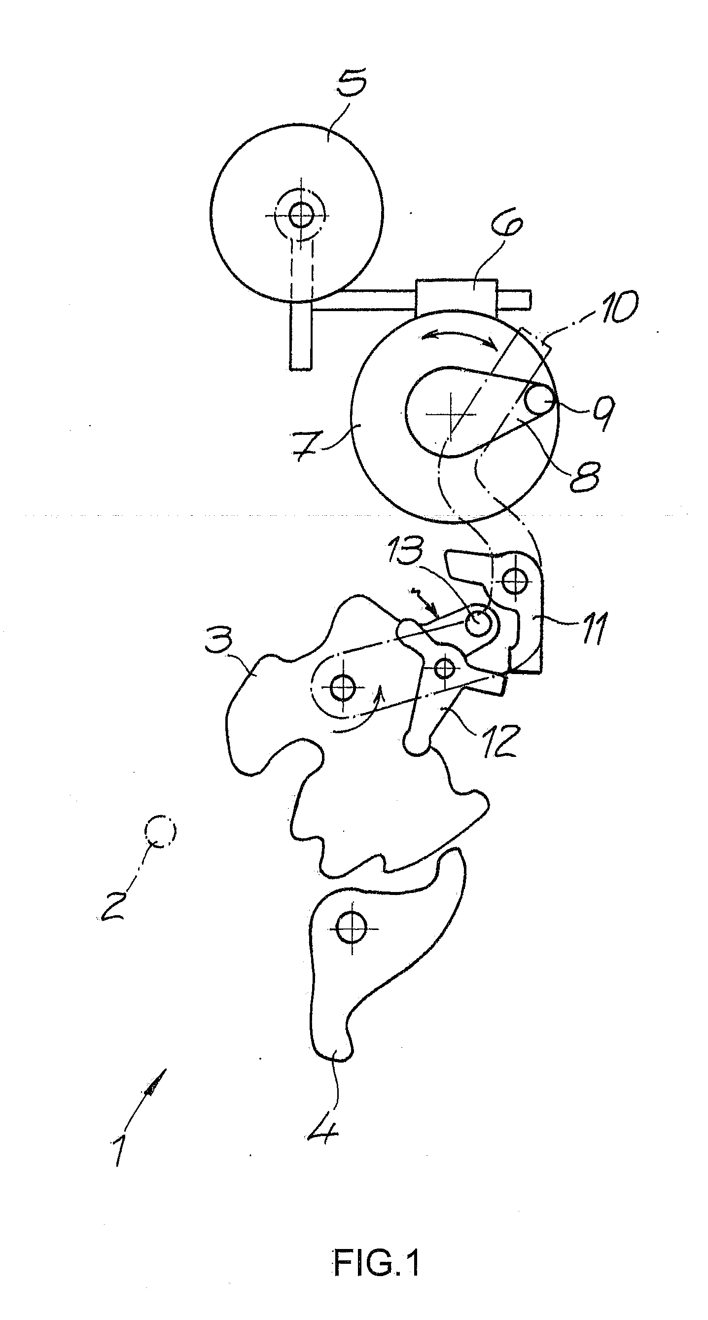
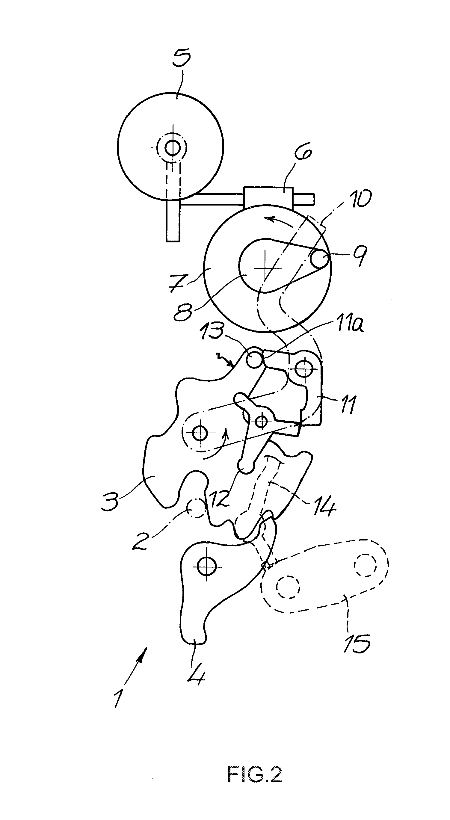
[0027]The figures show a motor vehicle door lock comprising as usual the mainly shown motor vehicle door lock 1 and a locking bolt 2—only indicated. The locking bolt 2 is normally mounted on a respective vehicle body, whilst the motor vehicle door lock 1 is secured to a not expressly shown motor vehicle door. The motor vehicle door lock or the motor vehicle door closure 1 contains a usual locking mechanism 3, 4 comprising a rotary latch 3 and a pawl 4.

[0028]The motor vehicle door lock furthermore contains a closing / opening device 5 to 12, designed in this case as a closing aid 5 to 12. The closing / opening device 5 to 12 contains at least one drive 5, 6, 7, 8, 9 and one lever actuating mechanism 10, 11, 12.

[0029]The drive 5, 6, 7, 8, 9 comprises a motor or electric motor 5 and a driving worm 6, arranged on a driving axis on an output side of the motor 5 and which is rotated with the aid of the motor 5. Rotations of the driving worm 6 cause a meshing worm gear 7 to rotate clockwise or...


PUM


Abstract

A motor vehicle door lock, comprising a locking mechanism (3, 4) and a closing / opening device (5 to 12), containing at least a drive (5, 6, 7, 8, 9) and a lever actuating mechanism (10, 11, 12), wherein the lever actuating mechanism (10, 11, 12) in its engaged state provides a mechanically effective connection between the drive (5, 6, 7, 8, 9) and the locking mechanism (3, 4) and is moved into its disengaged state by means of a triggering lever (14).

Description

FIELD OF THE INVENTION[0001]The present invention relates to a motor vehicle door lock comprising a locking mechanism and a closing / opening device, containing at least one drive and a lever actuating mechanism.BACKGROUND OF THE INVENTION[0002]The closing / opening device acts on the locking mechanism to either close or open it. This is achieved by means of the drive, which is being regularly acted upon during, for instance closing, when a respective motor vehicle door is in its intermediate closed position. The drive and the closing device then ensure that the motor vehicle door can be moved from its intermediate closed position or intermediate locked position to a fully closed position or fully locked position of the respective door lock.[0003]Because of the additional mechanical requirements and thus associated costs, such closing devices or closing aids are at present predominantly reserved for expensive and exclusive cars. Such vehicles also often feature heavier motor vehicle doo...

Claims


Application Information

Patent Timeline
Patent Type & Authority Applications(United States)
IPC IPC(8): E05B65/12E05C3/16
CPCE05B81/20E05B81/14E05B81/21E05B83/16Y10T292/1082Y10T292/1047Y10T292/108Y10T292/1059
Inventor SCHOLZ, MICHAELSCHIFFER, HOLGERREDDMANN, UWE
Owner KIEKERT AG
Why Eureka
Try Eureka