Converter System For Electrically Driving A Vehicle

Active Publication Date: 2016-05-26
ABB (SCHWEIZ) AG
View PDF2 Cites 5 Cited by
  • Summary
  • Abstract
  • Description
  • Claims
  • Application Information

AI Technical Summary

Benefits of technology

[0024]This preferred embodiment of the converter system enables an e

Problems solved by technology

Such a recuperation possibility imposes specific demands on the converter system.
These demands result in complicated and therefore expensive embodimen

Method used


Image

  • Converter System For Electrically Driving A Vehicle
  • Converter System For Electrically Driving A Vehicle
  • Converter System For Electrically Driving A Vehicle

Examples


Embodiment Construction

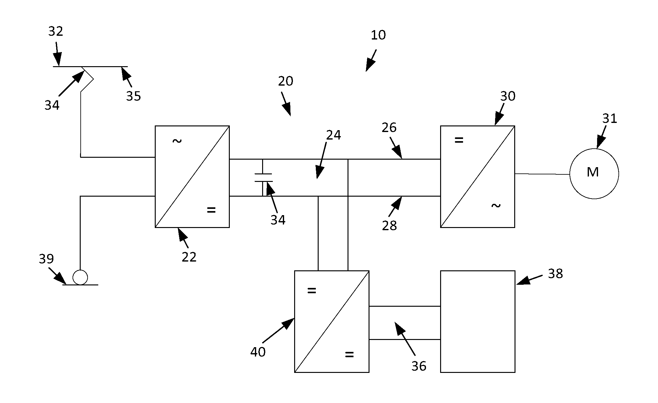
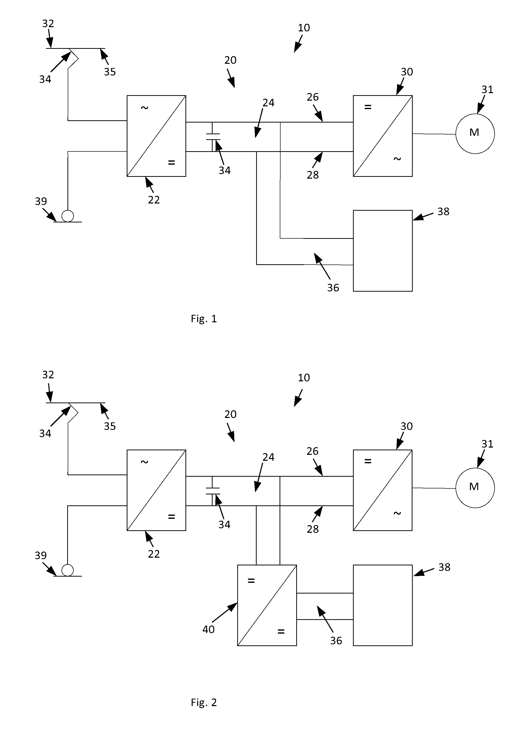
[0030]FIG. 1 shows an exemplary embodiment of an electrical rail vehicle 10 according to the invention and of a converter system 20 according to the invention. Rail vehicles are track-guided vehicles such as trains, locomotives and underground railways with conventional metal wheels as well as tires filled with air or the like. Further vehicle types are known to a person skilled in the art. The converter system according to the invention can also be used for electrical vehicles which are not track-guided, for example trolley buses.

[0031]The converter system 20 intended to electrically drive the rail vehicle 10 has a grid-side converter 22 and a DC link 24 with a first potential conductor 26 and a second potential conductor 28. The converter system 20 also has a motor-side converter 30, wherein the motor-side converter 30 allows a bidirectional flow of energy and is connected to one electrical machine 31 or to a plurality of electrical machines 31. The electrical machine(s) 31 is / are...


PUM


Abstract

A converter system for electrically driving a vehicle, including a grid-side converter, a DC link with at least a first and second potential conductors, and a motor-side converter. The motor-side converter allows a bidirectional flow of energy. The grid-side converter has a single phase on the input side and is connected to a supply grid. The grid-side converter is unidirectional and allows a flow of energy from the supply grid into the DC link. The DC link connects the grid-side converter to the motor-side converter and has a first electrical energy storage between the first and second potential conductors. The electrical energy storage is connected to the DC link via an electrical connection. The flow of energy from the DC link into the further electrical energy storage and the flow of energy from the further electrical energy storage into the DC link is able to be controlled.

Description

FIELD OF THE INVENTION[0001]The present invention relates to the field of converter systems for electrically driving a vehicle, in particular to converter systems. The present invention also relates to an electrical vehicle having a converter system.BACKGROUND OF THE INVENTION[0002]Such converter systems are well known to a person skilled in the art and have, in particular, a grid-side converter, a DC link and a motor-side converter, the grid-side converter being connected to a supply grid and the motor-side converter being connected to an electrical machine for driving a vehicle. In order to make it possible to drive the vehicle in an energy-efficient manner, such energy systems typically allow a bidirectional flow of energy, as a result of which the energy produced during electrical braking of the vehicle can be fed back into the supply grid, which operation is known to a person skilled in the art as recuperation of the braking energy. As a result of the recuperation possibility i...

Claims


Application Information

Patent Timeline
IPC IPC(8): B60L9/24B60L11/00B60M3/00B60L11/18
CPCB60L9/24B60M3/00B60L11/005B60L11/18H02J3/32B60L2200/26B60L2210/30H02M7/49B60L50/53B60L50/40B60L50/60Y02T10/72Y02T10/70
Inventor GUGGISBERG, BEATRONNER, BEAT
Owner ABB (SCHWEIZ) AG
Why Eureka
Try Eureka