Pressure sensor featuring pressure loading of the fastening element

a technology of fastening element and pressure sensor, which is applied in the field of pressure sensor, can solve the problems of particularly high cost and large quantity of pressure sensor manufacture, and achieve the effects of significant overload safety, cost-effectiveness, and simple and cost-effective design

Inactive Publication Date: 2008-03-18
ROBERT BOSCH GMBH
View PDF11 Cites 5 Cited by
  • Summary
  • Abstract
  • Description
  • Claims
  • Application Information

AI Technical Summary

Benefits of technology

[0003]The pressure sensor according to the exemplary embodiment of the present invention may have the advantage that a simple and cost-effective design is proposed for the manufacture of a pressure sensor. The pressure sensor according to the exemplary embodiment of the present invention is used in particular for measuring high pressures, the pressure sensor according to the exemplary embodiment of the present invention nonetheless exhibiting significant overload safety. Furthermore, it is also possible according to the exemplary embodiment of the present invention to use the pressure sensor for low pressures. The pressure sensor according to the exemplary embodiment of the present invention therefore has the advantage that cost-effective manufacture of a micromechanical sensor for low to high pressures (e.g., up to or over 1,000 bar) is possible. As a result, it is possible to cost-effectively provide a pressure sensor which is usable for a wide range of different pressures. This makes it possible to increase the quantities while further lowering costs. Moreover, the system according to the exemplary embodiment of the present invention makes it possible to separate the pressure medium and the analyzing circuit. It is particularly advantageous that the connections between the first and the second fixing area are only pressure-stressed. This means that the force action, which acts on the diaphragm area for measuring a pressure, has the effect that the first fixing area is pressed onto the second fixing area.
[0004]It may be particularly advantageous that semiconductor material and / or bulk micromechanics is / are used to manufacture the pressure sensor element, thereby making it possible to manufacture the pressure sensor element and thus the pressure sensor in a particularly cost-effective and reliable manner. Furthermore, it is an advantage that the pressure sensor is provided for high pressures up to approximately 1,000 bar or for high pressures exceeding 1,000 bar. Because of this and the usability in a wide pressure range, the pressure sensor is manufacturable particularly cost-effectively and in large quantities. Furthermore, it is an advantage that the fixing element, with respect to its coefficient of thermal expansion, is designed to be adapted to the sensor element. This makes it possible that, due to temperature fluctuations, only minor stresses are applied to the sensor element and that the pressure sensor is usable not only in a wide pressure range but also in a wide temperature range.
[0005]It may also be advantageous that a connecting material is provided between the first fixing area and the second fixing area, the connecting material being comparatively soft. As a result, mechanical stresses due to temperature fluctuations are also able to be effectively compensated for. Furthermore, it is an advantage that resistor elements are provided in the diaphragm area, thereby making it possible to measure pressures in wide pressure ranges via a simple arrangement and thus in a cost-effective manner. Furthermore, it is advantageous that the connecting surface between the first fixing area and the second fixing area is provided to be parallel or inclined, i.e., at an acute angle, with respect to the diaphragm plane, thereby resulting in manifold possibilities for varying the pressure sensor according to the exemplary embodiment of the present invention. It is also advantageous that the cross section of the fixing element tapers in the direction of the second fixing area. This makes it possible in a simple manner to assemble the sensor chip in a centered position.

Problems solved by technology

Because of this and the usability in a wide pressure range, the pressure sensor is manufacturable particularly cost-effectively and in large quantities.

Method used


Image

  • Pressure sensor featuring pressure loading of the fastening element
  • Pressure sensor featuring pressure loading of the fastening element
  • Pressure sensor featuring pressure loading of the fastening element

Examples


Embodiment Construction

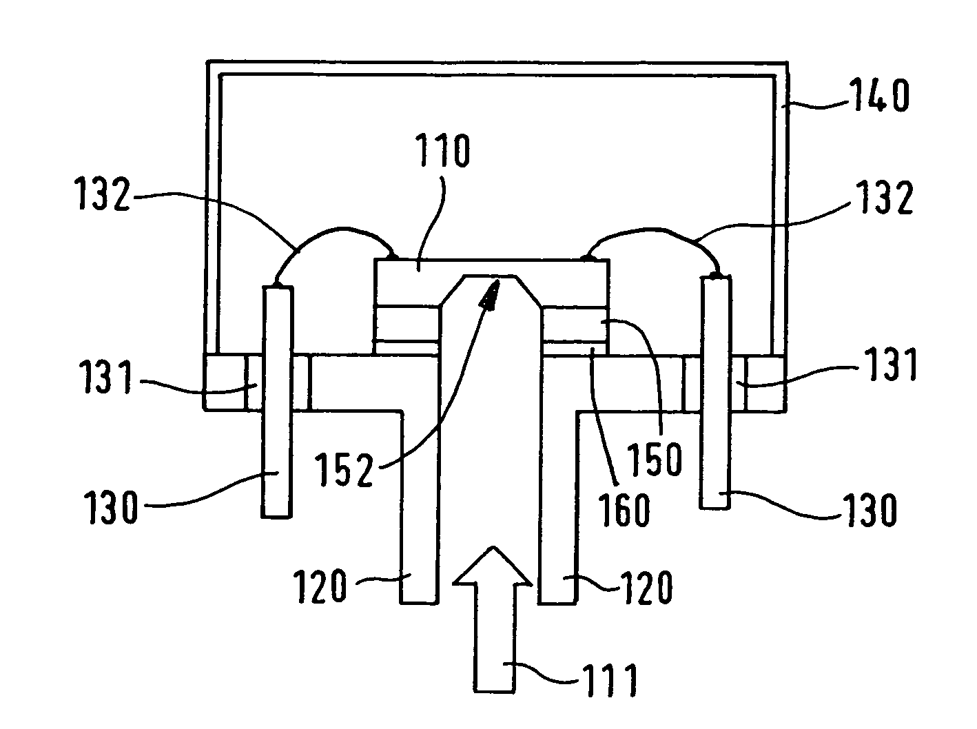
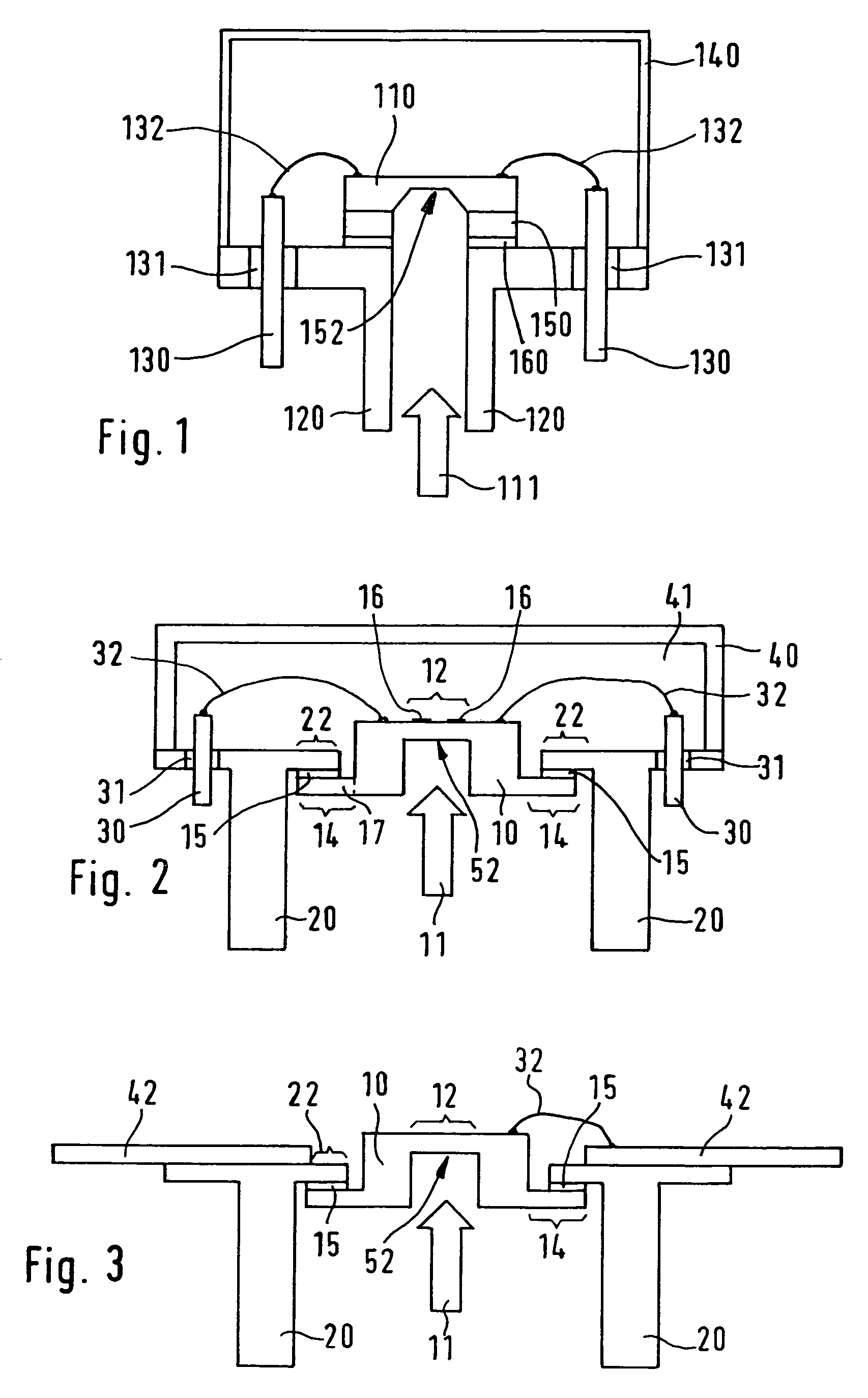
[0012]FIG. 1 shows the generally common design of micromechanical silicon pressure sensors. A silicon substrate 110 is provided with a cavern 152 which creates a diaphragm which is not indicated in detail by a reference numeral. Silicon substrate 110 is connected to a glass 150 which is provided with a bore and is soldered onto a socket 120 via a solder 160. Socket 120 as a single piece is connected to a pressure connecting piece. Furthermore, measuring shunts (not indicated in detail by a reference numeral), which are situated on the top side of silicon substrate 110, are connected to a terminal post 130 via one or multiple contact wires 132, the terminal posts being electrically isolated from socket 120 by a glass insulation 131. Cavern 152 of silicon substrate 110 has a typical etch bevel which has approximately the shape of the frustum of a pyramid. This results in a trapezoidal cross section.

[0013]This frustum of a pyramid-shaped recess underneath the sensor diaphragm results w...


PUM

PropertyMeasurementUnit
pressuresaaaaaaaaaa
angleaaaaaaaaaa
pressureaaaaaaaaaa

Abstract

A pressure sensor having a pressure sensor element, the pressure sensor element having a diaphragm area and a first fixing area, the pressure to be measured exerting a force action on the diaphragm area, the first fixing area being connected to a second fixing area of a fixing element to fix the pressure sensor element, and the first fixing area and the second fixing area being pressure-loaded by the force action.

Description

FIELD OF THE INVENTION[0001]The present invention is directed to a pressure sensor.BACKGROUND INFORMATION[0002]Micromechanical silicon pressure sensors may have a diaphragm created by inserting a cavern into a silicon chip. Such a silicon sensor is discussed in Unexamined German Patent Application No. 199 57 556, for example. In this case, the cavern is created via anisotropic KOH etching for example.SUMMARY OF THE INVENTION[0003]The pressure sensor according to the exemplary embodiment of the present invention may have the advantage that a simple and cost-effective design is proposed for the manufacture of a pressure sensor. The pressure sensor according to the exemplary embodiment of the present invention is used in particular for measuring high pressures, the pressure sensor according to the exemplary embodiment of the present invention nonetheless exhibiting significant overload safety. Furthermore, it is also possible according to the exemplary embodiment of the present inventi...

Claims


Application Information

Patent Timeline
Patent Type & Authority Patents(United States)
IPC IPC(8): G01L7/00G01L9/00
CPCG01L19/147G01L19/148H01L2224/48091H01L2924/00014H01L2924/10253H01L2924/00
Inventor MUCHOW, JOERGBENZEL, HUBERTWEBER, HERIBERTSCHAEFER, FRANK
Owner ROBERT BOSCH GMBH
Why Eureka
Try Eureka