Rubber mount for supporting a profile rod

a technology of profile rods and mounting brackets, which is applied in the direction of machine supports, transportation and packaging, and torsion springs, etc., can solve the problems of difficult installation on the stabilizer, high production costs of the stabilizer supplier, and relatively complex geometry of the axial stabilizer, etc., to achieve simple and cost-effective design, easy installation

Inactive Publication Date: 2006-09-19
ZF FRIEDRICHSHAFEN AG
View PDF12 Cites 6 Cited by
  • Summary
  • Abstract
  • Description
  • Claims
  • Application Information

AI Technical Summary

Benefits of technology

[0009]It is an object of the invention to provide a rubber mount for supporting a profile rod, such as an automobile stabilizer, whereby the mount has a simple and cost-effective design and can be easily installed on the profile rod already at the manufacturer's site with only a few installation steps.
[0011]The proposed rubber mount includes, in a manner known in the art, an elastomer mounting body with an essentially cylindrical hollow space that is open at axial ends for receiving the profile rod to be supported. The mounting body also includes at least one axially continuous slot which at least enables installation of the mounting body on the profile rod by pushing the mounting body onto the profile rod in the radial direction. After installation, the mounting body can be secured to profile rod with clamping means (bracket) by reducing the opening angle of the slot formed in the mounting body.
[0012]According to an aspect of the invention, the proposed bracket, unlike conventional brackets, is formed on the mounting body itself. Bracket and mounting body are therefore formed as a single piece, i.e., the bracket is an integral component of the elastomer mounting body. Because this type of elastomer mounting body, unlike conventional mounts, is no longer surrounded by a metallic bracket, the slot of the bracket can be easily spread apart for increasing the opening angle when the mount is pushed onto the rod. This significantly facilitates installation.
[0019]The rubber strap with the snap-in hook and the snap-in hook receptacle, which can be formed as a groove, extend in the axial direction of the rubber mount and essentially along the entire mounting body. When the rubber mount is installed, the outer periphery of the rubber mount has an essentially smooth surface; in particular, the slot is almost completely covered, thereby preventing foreign bodies from entering the slot.
[0020]In another advantageous embodiment of the rubber mount according to the invention, the inner surfaces of the slot are profiled. This profile, which can be formed, for example by mutually complementary steps on the opposing inner surfaces of the slot, aids in securing the mounting body, which is clamped with the bracket, on the profile rod.
[0021]The rubber mount of the invention can be easily handled during installation on a profile rod, preferably on a stabilizer. Depending on the design of the mount, the mount needs only to be pushed radially onto the stabilizer rod at the desired axial position and placed around the stabilizer rod by swinging open its half shells. The mount is then affixed on the rod with the bracket that advantageously is an integral component of the elastomer mounting body. The manufacturer can therefore preinstall the mounts on the stabilizers before shipping the stabilizers to the customer, thus reducing installation costs and complexity. In addition, as easily seen, the mount has a very simple design. Mounting body and bracket can be produced in a single manufacturing step by designing a suitable injection mold.

Problems solved by technology

The first approach entails high production costs for the supplier of the stabilizers, because the mounts can be difficult to install on the stabilizer, frequently requiring several operating steps.
The axial stabilizer geometry can be relatively complex, so that moving the rubber in the axial direction can be difficult at least in certain sections.
This variant is not user-friendly, because the elastomer mounting body may be difficult to move, as described above.
However, a considerable force or a suitable tool is still required to radially press the mounting body onto the profile rod.

Method used


Image

  • Rubber mount for supporting a profile rod
  • Rubber mount for supporting a profile rod
  • Rubber mount for supporting a profile rod

Examples


Embodiment Construction

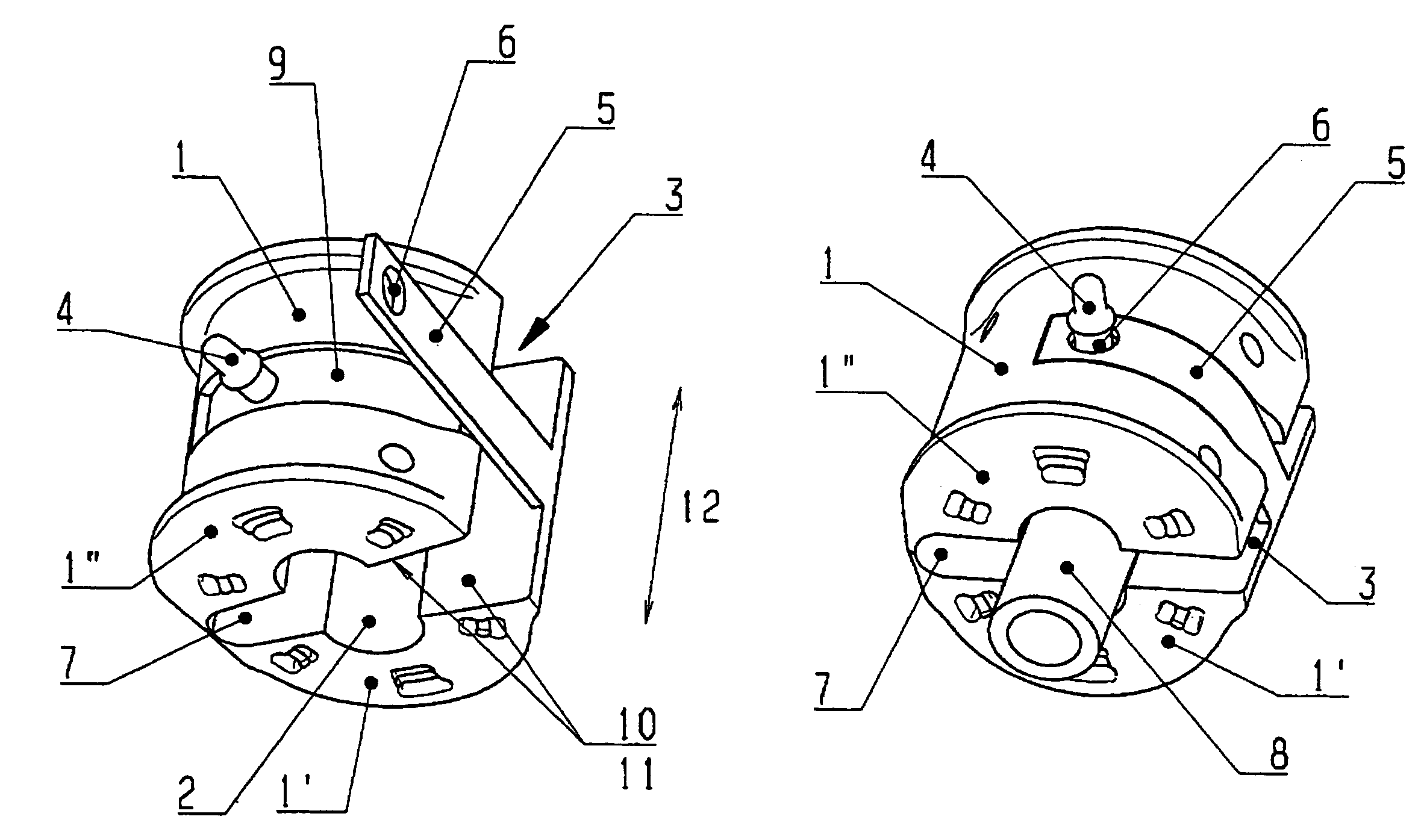
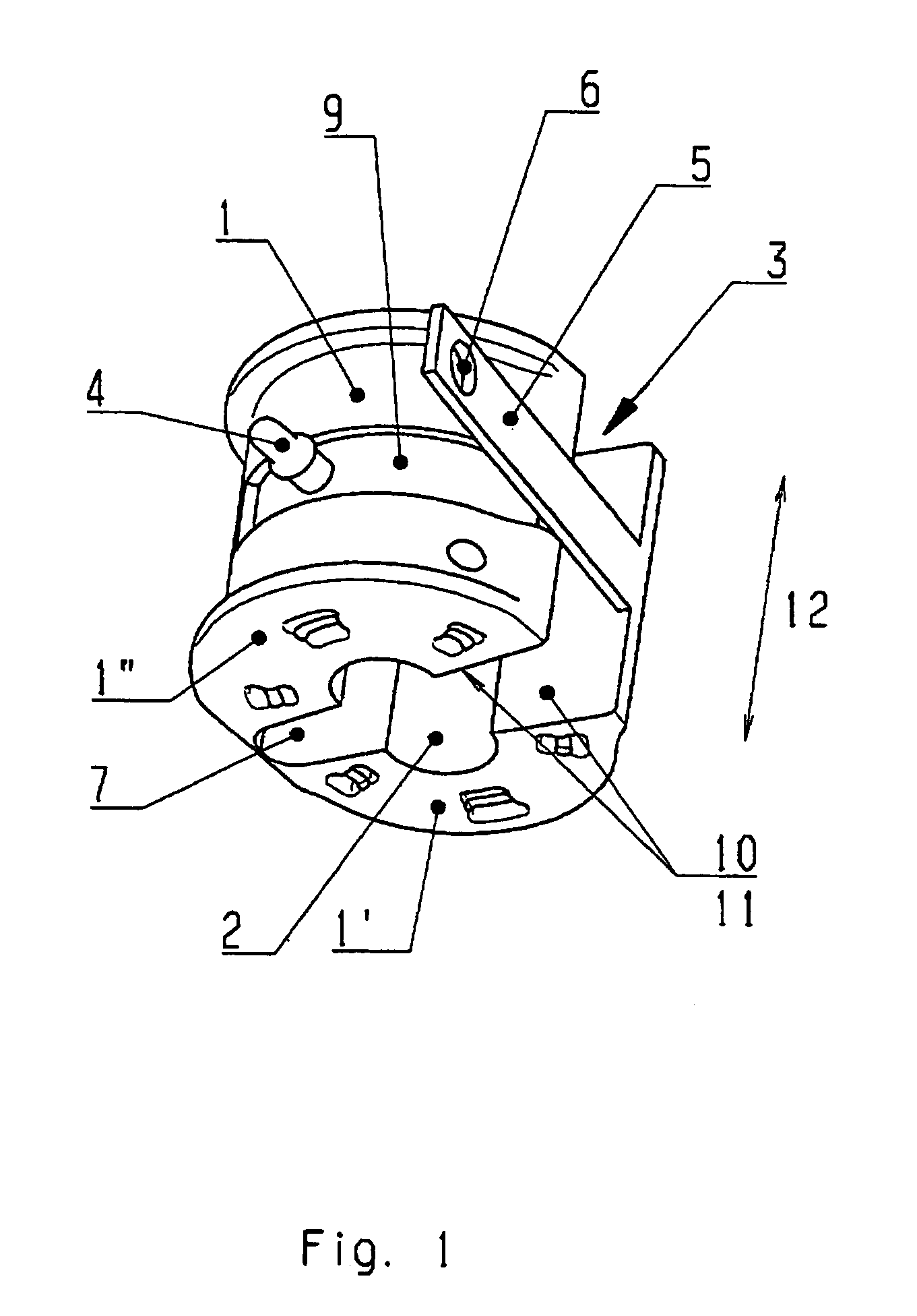
[0027]FIG. 1 shows a perspective view of an advantageous embodiment of the mount according to the invention before installation on a profile rod 8 (not shown in FIG. 1). FIG. 1 shows the elastomer mounting body 1 and the bracket 4, 5, 6 formed as an integral component of the mounting body 1. The mounting body 1 includes an essentially cylindrical hollow space 2 that is open in the axial direction 12 (the exact geometry depends, of course, on the geometry of the supported profile rod 8) and an axially continuous slot 3. In the depicted exemplary mount, the mounting body 1 likewise has an axially continuous slit 7 located on the side opposite the slot 3. The slit 7 is not continuous in the radial direction between the hollow space 2 and the outside. Accordingly, the mounting body 1 is composed of two connected half shells 1′, 1″ and can be easily swung open and placed around the profile rod 8 for subsequent installation on the profile rod 8. A significant feature of the invention is t...


PUM


Abstract

The invention is directed to a rubber mount for supporting a profile rod, and more particularly to a rubber mount for supporting a stabilizer of an automobile. It is the object of the invention to provide a mount of the aforedescribed type that can be installed on the profile rod easily, with only a few operating steps, preferably already at the manufacturer's site, and that has an simple and cost-effective construction. The proposed rubber mount includes an elastomer mounting body with an axially continuous slot which enables the mounting body to be pushed radially onto the profile rod for installation thereon. After installation, the mounting body can be secured with a clamping means (bracket), which according to the invention is formed on the mounting body itself. Stated differently, the bracket and mounting body are formed as a single piece, and the bracket is an integral component of the elastomer mounting body.

Description

BACKGROUND OF THE INVENTION[0001]1) Field of the Invention[0002]The invention relates to a rubber mount for supporting a profile rod, and more particularly to a rubber mount for supporting a stabilizer for an automobile. However, the mount is not limited to this application.[0003]2) Description of the Related Art[0004]Rubber mounts are used for elastic support of profile rods in various applications. For example, the stabilizers of automobiles are customarily supported by suitable rubber mounts. The stabilizer is hereby received in an essentially cylindrical hollow space of an elastomer mounting body that is open in the axial direction on both ends. The stabilizer with the mounting body is then attached to other components, for example an auxiliary frame of the vehicle, with a clamping element (bracket) that encompasses the mounting body.[0005]In practical applications, the stabilizers are either supplied with preinstalled mounts that are vulcanized on the stabilizer, or the mounts ...

Claims


Application Information

Patent Timeline
Patent Type & Authority Patents(United States)
IPC IPC(8): F16F1/38B60G21/055
CPCB60G21/0551F16F1/3842F16F1/3835B60G2204/1222B60G2204/4108B60G2204/41043
Inventor KUMPER, BERND
Owner ZF FRIEDRICHSHAFEN AG
Why Eureka
Try Eureka