Suppressor device

a technology of interference suppression and suppressor, which is applied in the direction of cross-talk/noise/interference reduction, coupling device connection, association of printed circuit non-printed electric components, etc., can solve problems such as affecting the operation of the circuit of electronic appliances, and achieve simple and cost-effective design, effective shielding, and suitable for mass production

Inactive Publication Date: 2007-09-11
CONTINENTAL AUTOMOTIVE GMBH
View PDF12 Cites 6 Cited by
  • Summary
  • Abstract
  • Description
  • Claims
  • Application Information

AI Technical Summary

Benefits of technology

[0006]An object of the invention is to provide an interference suppression device which, given a simple and cost-effective design, ensures effective shielding against, in particular, radio-frequency interference radiation and is also suitable for mass production.

Problems solved by technology

Via the cutouts and metal parts, including the plug elements, which protrude into the housing interior from the outside, radio-frequency interference radiation of, in particular, >approximately 400 MHz is conducted and irradiated into the interior of the metal housing, which is actually provided for shielding purposes, and may impair the operation of the circuit of the electronic appliance owing to the high-energy radiation.

Method used


Image

  • Suppressor device
  • Suppressor device
  • Suppressor device

Examples


Embodiment Construction

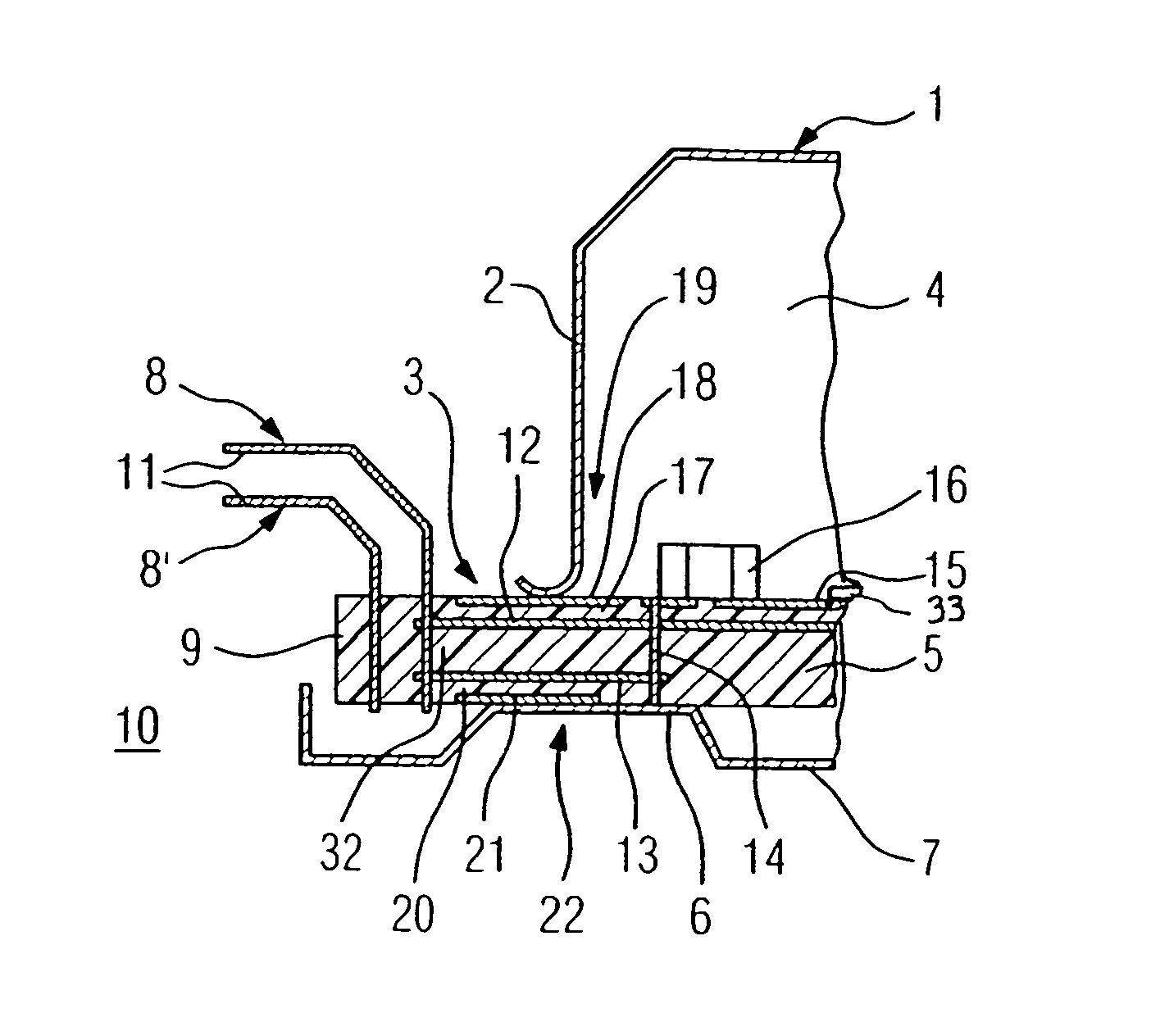
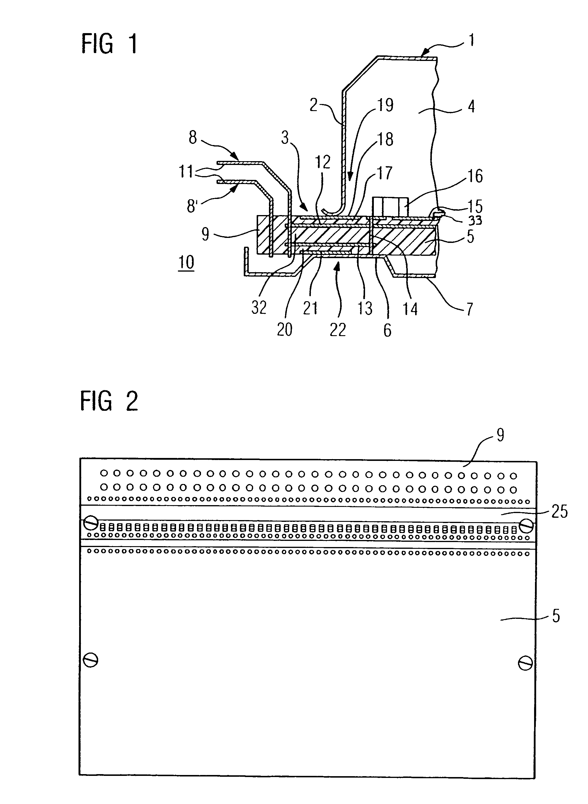
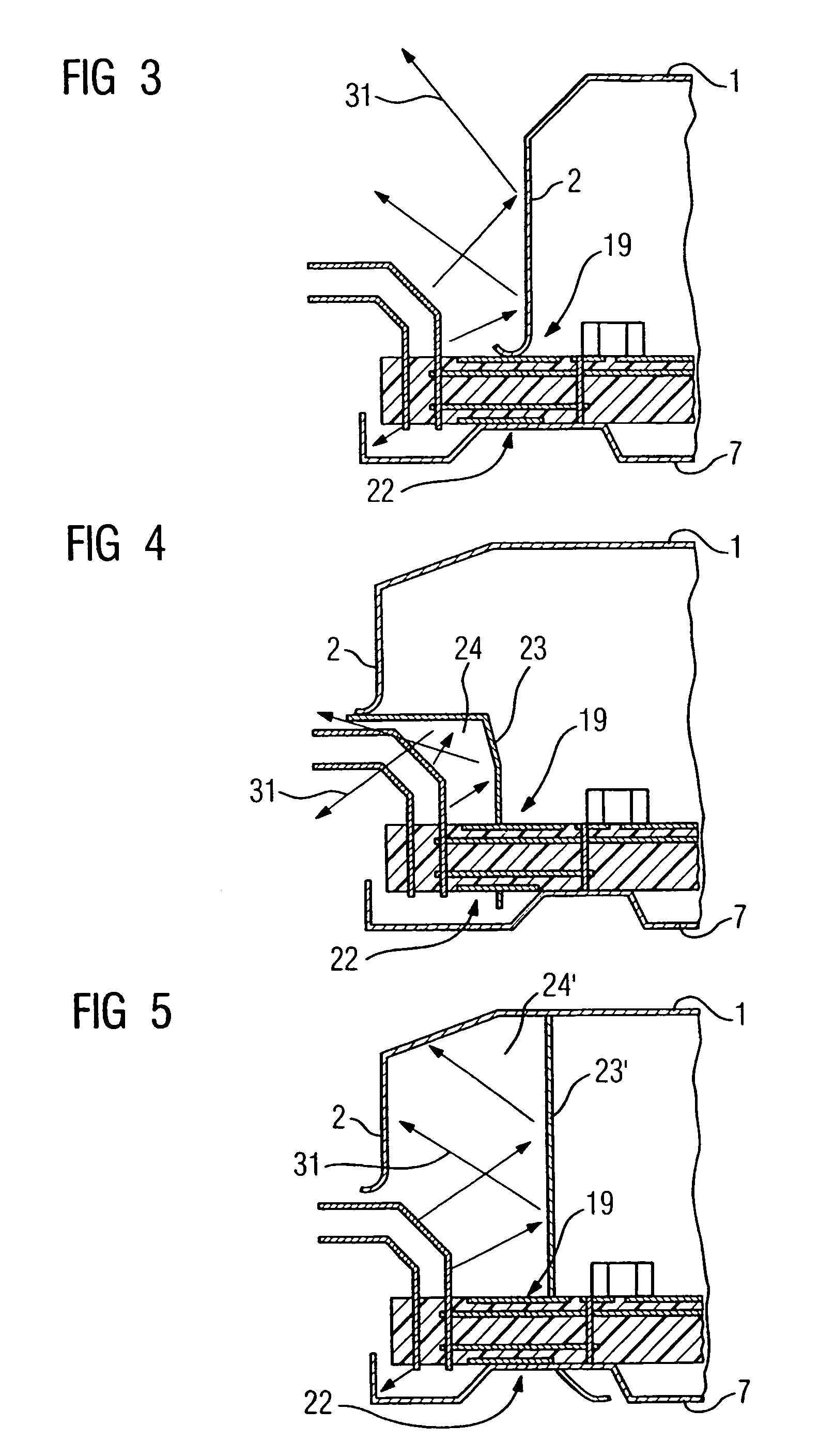
[0039]The interference suppression devices illustrated in the figures have a housing 1 made of sheet metal for an electronic appliance, which has an opening 3 at a lateral housing wall 2. A printed circuit board 5, which rests on elevated embossed areas 6 of the base 7 of the housing 1, is arranged in the housing interior 4. The printed circuit board 5 bears an electronic circuit 33 with which contact can be made from the outside via plug elements 8, 8′ and which is fed low-frequency signals via the plug elements 8, 8′.

[0040]The printed circuit board 5 has a part 9, which extends through the opening 3 to the housing exterior 10, the base 7 of the housing 1 protruding laterally and covering the entire lower region of the printed circuit board 5, including the part 9.

[0041]The plug elements 8, 8′ have plug pins 11, which protrude horizontally away from the housing 1 and onto which a corresponding opposing plug pair (not shown) can be plugged. Those ends of the plug elements 8, 8′ whic...


PUM


Abstract

A suppressor device for an electronic device comprising a plug-in device, comprising at least one plug element, which is arranged on a electrically conducting housing of the electronic device. A printed circuit board is arranged in the housing and bears an electronic circuit leading to the plug element. A capacitor is connected to the plug element and to the potential of the housing. The capacitor is arranged on the printed circuit board which protrudes from the inner part of the housing through an opening with a part thereof and which is also extends from the inner part of the housing to the outer side of the housing. The plug element is conductively connected to the capacitor and the circuit on the part of the printed circuit board located on the outer part of the housing.

Description

PRIORITY CLAIM[0001]This is a U.S. national stage of application No. PCT / DE2003 / 002031, filed on Jun. 18, 2003. Priority is claimed on the following application(s): Country: Germany, Application No.: 102 33 318.1, Filed: Jul. 22, 2002.BACKGROUND OF THE INVENTION[0002]1. Field of the Invention[0003]The invention relates to an interference suppression device for an electronic appliance, the interference suppression device having a plug device, with at least one plug element arranged on an electrically conductive housing of the electronic appliance, a printed circuit board arranged in the housing and bearing an electrical and / or electronic circuit to which the plug element is connected, and a capacitor connected on the one hand to the plug element and on the other hand to the potential of the housing.[0004]2. Description of the Prior Art[0005]It is known with such interference suppression devices to pass the plug elements of the plug device through cutouts in a plug cover into the hous...

Claims


Application Information

Patent Timeline
Patent Type & Authority Patents(United States)
IPC IPC(8): H05K9/00H01R13/648H01R13/658H01R13/66H04B15/02H05K1/00H05K1/02H05K1/16
CPCH01R13/6625H01R13/6658H04B15/02H05K1/162H05K9/0066H01R13/6581H01R13/719H05K1/0216H05K1/0298H05K2201/09672H05K2201/10189H05K2201/10371H01R13/6466H01R13/6587H01R24/30
Inventor BERBERICH, REINHOLD
Owner CONTINENTAL AUTOMOTIVE GMBH
Why Eureka
Try Eureka