Valve arrangement for controlling a brake system of a trailer vehicle

a brake system and valve arrangement technology, applied in the direction of braking systems, functional valve types, brake action initiations, etc., can solve the problems of braking the trailer vehicle after a leakage or hose tearoff, and achieve the effect of reducing the cost of the valve arrangement and shortening the compressed air lines with relatively large dimensions

Active Publication Date: 2015-02-03
KNORR-BREMSE SYST FUER NUTZFAHRZEUGE GMBH
View PDF26 Cites 5 Cited by
  • Summary
  • Abstract
  • Description
  • Claims
  • Application Information

AI Technical Summary

Benefits of technology

[0025]As a result, the tear-off function of the tear-off valve and the function of the shuttle valve from the prior art described in detail at the beginning are integrated into the second valve device, which may be formed by a single 3 / 2 way valve. As a result, the abovementioned two functions can be carried out by just a single valve instead of by two valves, which results in a valve arrangement which is more cost-effective and simpler in design.
[0027]If, on the other hand, as in the case of the exemplary embodiments and / or exemplary methods of the present invention, the compressed air from the trailer-vehicle-side compressed air supply is used not only for the shunting function but also for the other functions of releasing the spring brake or keeping the spring brake released, and this compressed air supply is arranged centrally, compressed air lines with relatively large dimensions can be made shorter. Because a relatively small quantity of air is sufficient to actuate the second control valve device with control compressed air, the compressed air lines which conduct the control compressed air from the “supply” coupling head to the second valve device can be given relatively small dimensions. These measures therefore also contribute advantageously to reducing the costs of the valve arrangement.

Problems solved by technology

However, at the same time, the service brake pressure is also present at the service brake connections 64, as a result of which the service brake is applied, with the result that the requirement for braking of the trailer vehicle after a leak or tearing off of a hose is met.

Method used


Image

  • Valve arrangement for controlling a brake system of a trailer vehicle
  • Valve arrangement for controlling a brake system of a trailer vehicle
  • Valve arrangement for controlling a brake system of a trailer vehicle

Examples


Embodiment Construction

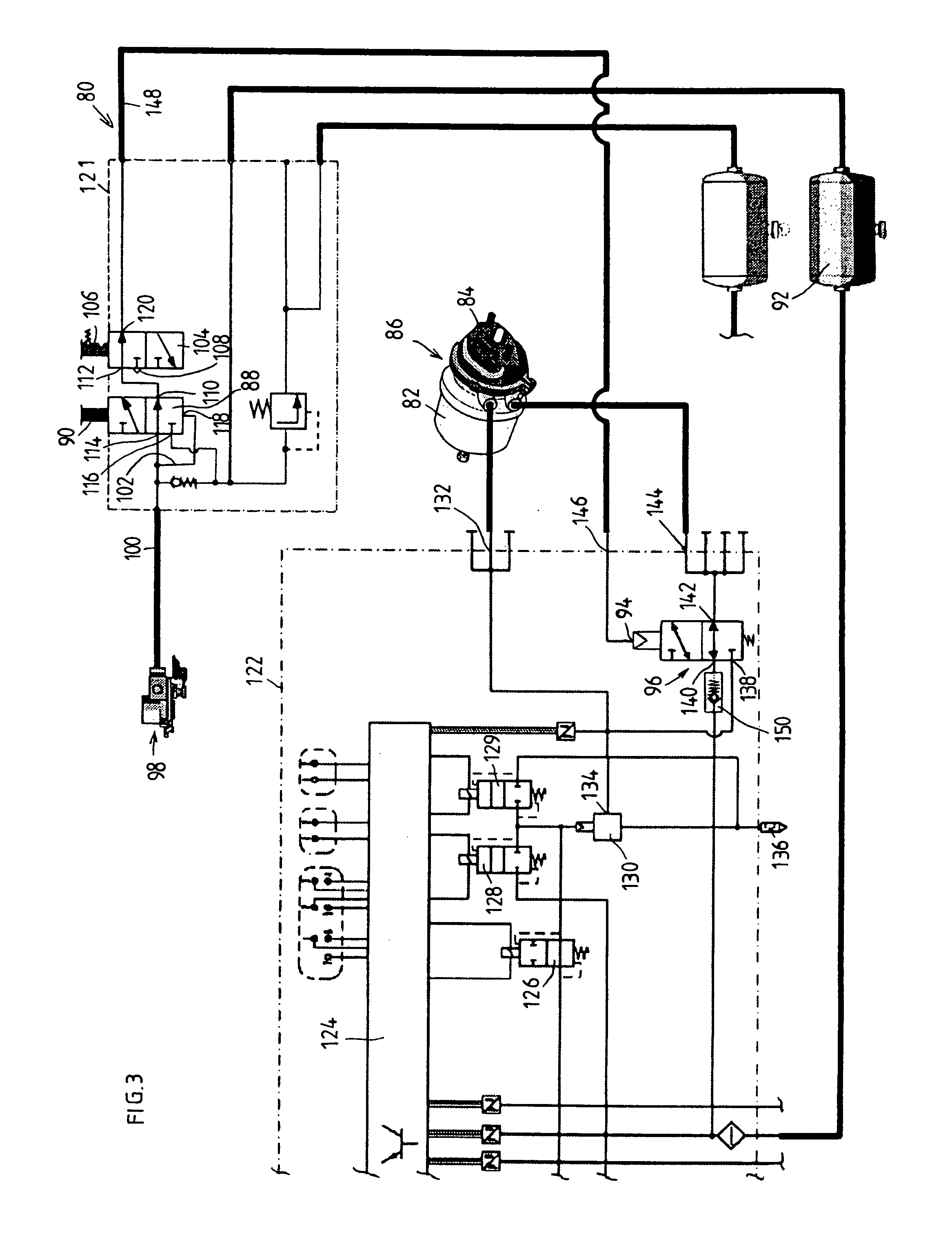
[0034]In the exemplary embodiment which is shown in FIGS. 3 and 4 for a valve arrangement 80 according to the present invention for controlling a brake system, comprising at least one spring brake cylinder 82 and at least one service brake cylinder 84, of a trailer vehicle of a traction vehicle-trailer combination, a combination cylinder 86 is used as a brake cylinder which comprises, on the one hand, the service brake cylinder 84 as an active service brake, which is ventilated in order to apply the brake and vented in order to release the brake, and, on the other hand, the spring brake cylinder 82 with a storage spring as a passive parking brake, which is vented in order to apply the brake and ventilated in order to release the brake. In this context, the service brake cylinder 84 and the spring brake cylinder 82 are arranged in series. The design of such a combination cylinder 86 is adequately known, for example from DE 29 23 359 C2. For this reason, more details will not be given...


PUM


Abstract

A valve arrangement for controlling a brake system, comprising at least one spring brake cylinder and at least one service brake cylinder, of a trailer vehicle of a traction vehicle-trailer combination, characterized in that said valve arrangement includes a 3 / 2 way valve which, as a function of the control pressure present at its control inlet, connects either its connection, which is connected to an outlet of a control valve device in order to generate service brake pressure for the at least one service brake cylinder, or connects its connection, which is connected to a trailer-vehicle-side compressed air supply, to its further connection which is connected to the at least one spring brake cylinder.

Description

FIELD OF THE INVENTION[0001]The present invention is based on a valve arrangement for controlling a brake system, comprising at least one spring brake cylinder and at least one service brake cylinder, of a trailer vehicle for a traction vehicle-trailer combination.BACKGROUND INFORMATION[0002]In modern trailer vehicles of traction vehicle-trailer combinations, what are referred to as combination cylinders are usually used as brake cylinders, which combination cylinders comprise, on the one hand, a service brake cylinder as an active service brake, which is ventilated in order to apply the brake and vented in order to release the brake, and, on the other hand, a spring brake cylinder as a passive parking brake, which is vented in order to apply the brake and ventilated in order to release the brake.[0003]FIG. 1 shows a park / shunt valve arrangement 1 from the prior art, which park / shunt valve arrangement 1 serves on the one hand, in a trailer vehicle of a traction vehicle-trailer combi...

Claims


Application Information

Patent Timeline
Patent Type & Authority Patents(United States)
IPC IPC(8): B60T13/00B60T13/68B60T15/02
CPCB60T13/683B60T15/027Y10T137/7837
Inventor MEDERER, MARTIN
Owner KNORR-BREMSE SYST FUER NUTZFAHRZEUGE GMBH
Why Eureka
Try Eureka