Touch Display Panel and Associated Method

a technology of touch display and associated methods, which is applied in the field of touch display panels, can solve the problems of increasing the cost of the touch sensing mechanism, and the cost of the resolution and accuracy so as to increase the resolution of the touched position, the cost of the touch sensing mechanism, and the cost of the effect of increasing the cos

Inactive Publication Date: 2011-08-04
ILI TECHNOLOGY CORPORATION
View PDF2 Cites 26 Cited by
  • Summary
  • Abstract
  • Description
  • Claims
  • Application Information

AI Technical Summary

Benefits of technology

[0004]A capacitive touch sensor senses a capacitance variation caused by a touch of a user by defining a plurality of electrodes in a sensing area, and thus calculating/analyzing a touched position. In the touch sensor, a resolution and accuracy of the touched position are associated with cost. To increase the resolution of the touched position, electrodes insulated from each other are defined in the sensing area, capacitance variations of the electrodes are separately sensed to resolve the touched position. However, for this tec

Problems solved by technology

In the touch sensor, a resolution and accuracy of the touched position are associated with cost.
However, for this technique, the touch sensor (and associated circuits) needs a large amount of pins to support the increased electrodes, thereby subst

Method used


Image

  • Touch Display Panel and Associated Method
  • Touch Display Panel and Associated Method
  • Touch Display Panel and Associated Method

Examples


Embodiment Construction

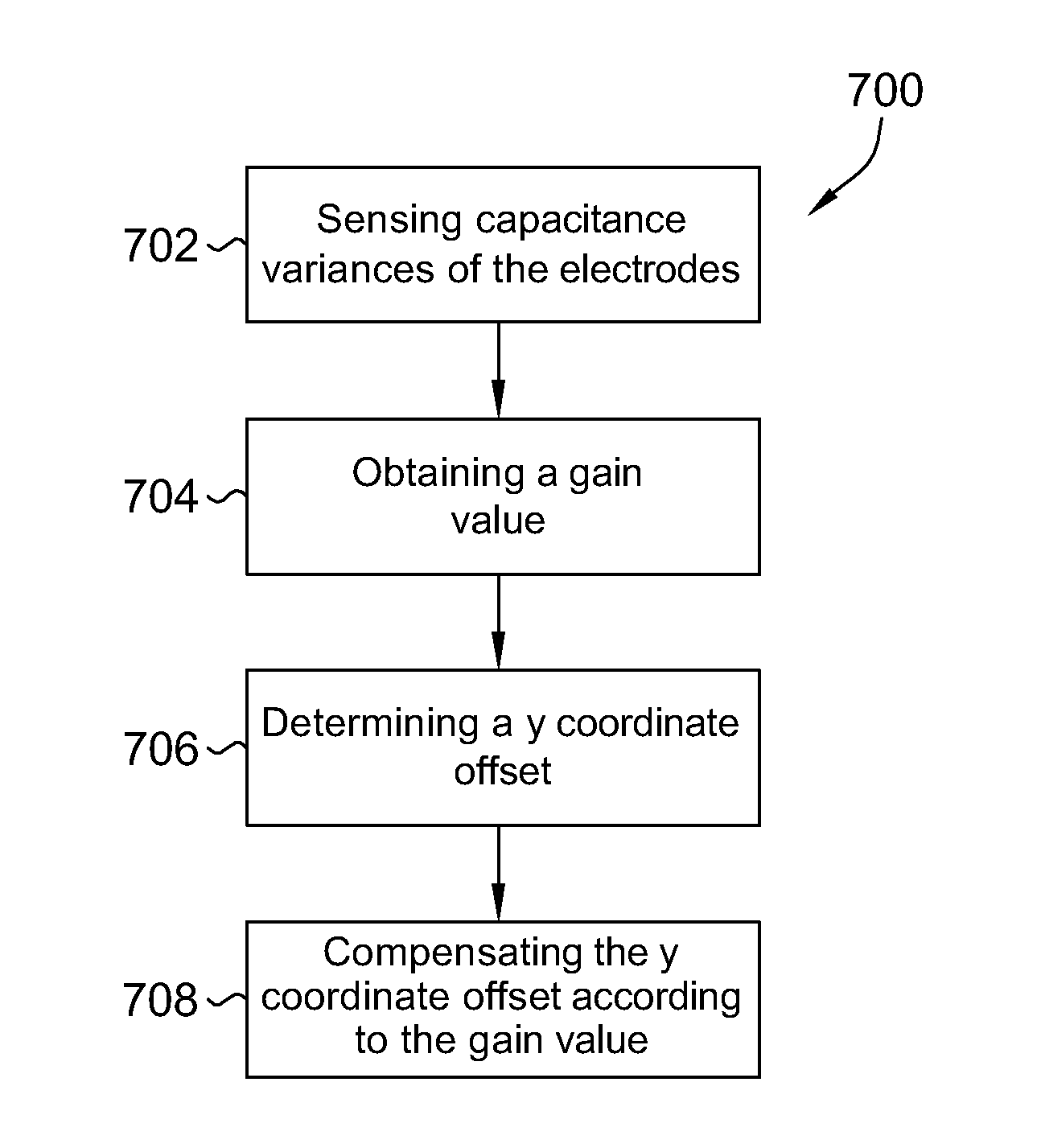
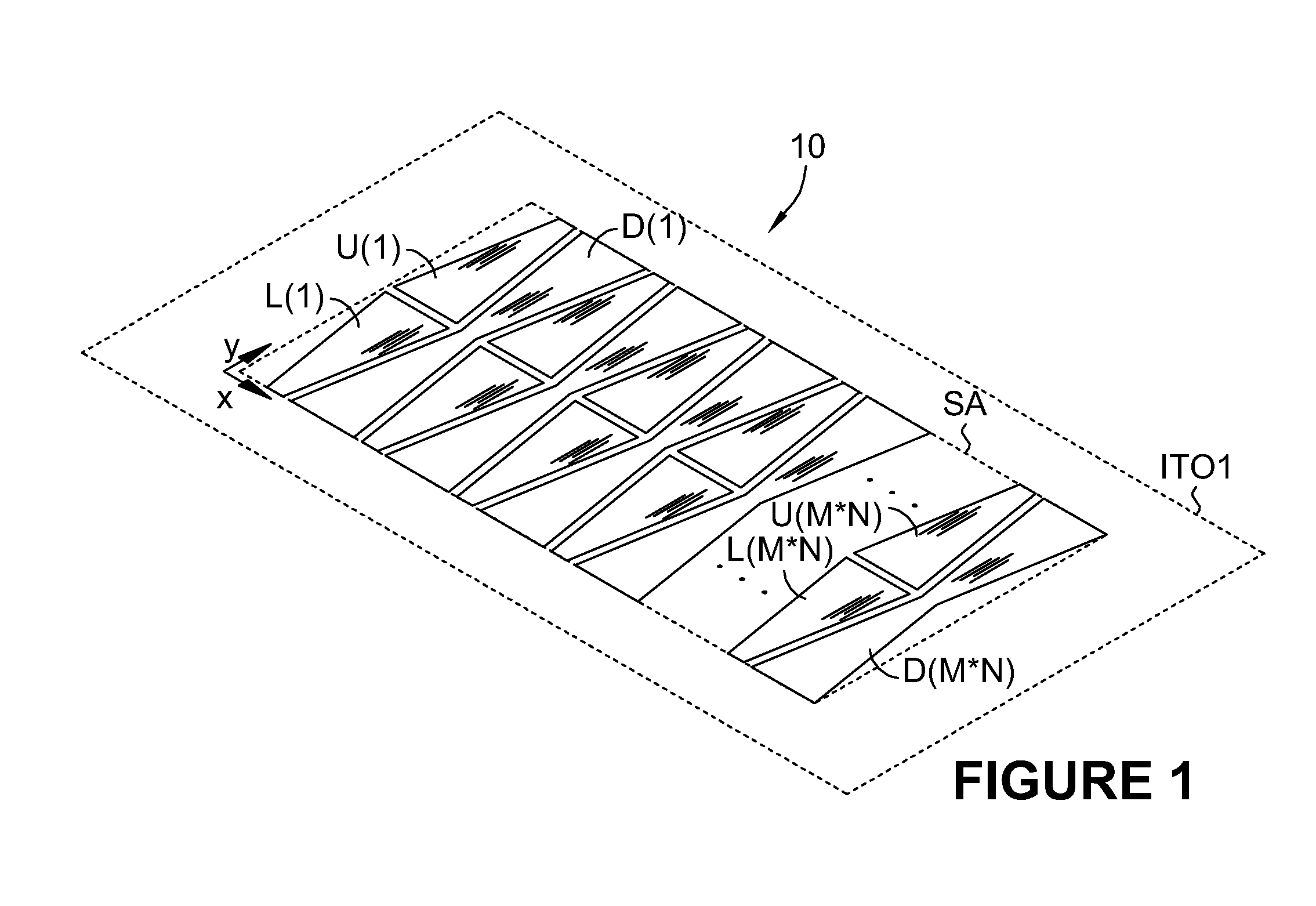
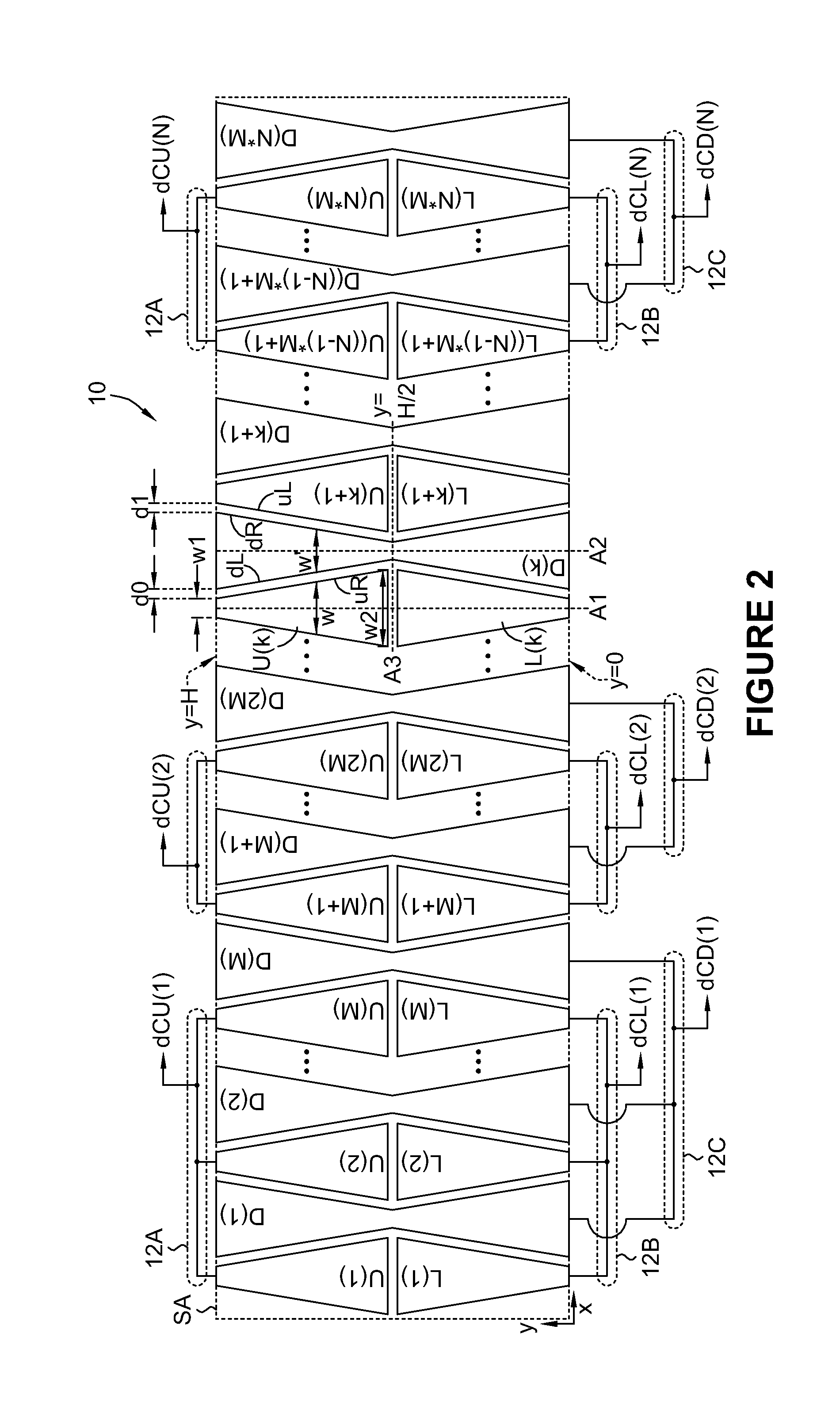
[0025]FIG. 1 and FIG. 2 are schematic diagrams of a touch sensor 10 in accordance with an embodiment of the present invention. Referring to FIG. 1, the touch sensor 10 is realized by a plurality of electrodes U(1) to U(M*N), a plurality electrodes L(1) to L(M*N), and a plurality of electrodes D(1) to D(M*N), where M and N are constant integers, M is greater than or equal to 1, and N is greater than 1. The electrodes are disposed in a sensing area SA of one conductive layer ITO1, which is an indium tin oxide (ITO) transparent conductive layer. In the sensing area SA, the electrodes are for coupling charges and capacitance variations caused by a touch of a user, and other structures (not shown) are adopted to insulate the outside of the sensing area SA from the touch of the user. When a touch screen is realized, the sensing area SA is regarded as a visible area, such that an image of the display panel is seen through the sensing area SA. Supposed that a xy plane is defined in the sens...


PUM


Abstract

A conductive layer of a touch sensor and a pixel electrode conductive layer of a display panel are integrated to a touch display panel during the same fabrication. The touch sensor defines a plurality of sensor groups that are insulated from each other in a same conductive layer, and each of the sense groups is divided into a plurality of mutually-coupled first electrodes, a plurality of mutually-coupled second electrodes and a plurality of mutually-coupled third electrodes. The first electrodes and the third electrodes are insulated from each other and are horizontally interlaced. The first electrodes and the second electrodes are insulated from each other and are located on opposite sides of a horizontal symmetry axis. A gain for compensating a vertical coordinate of a touch position is introduced according to capacitance variances of the first electrodes and the second electrodes.

Description

CROSS REFERENCE TO RELATED PATENT APPLICATION[0001]This patent application is based on Taiwan, R.O.C. patent application No. 099102683 filed on Jan. 29, 2010.FIELD OF THE INVENTION[0002]The present invention relates to a touch display panel integrated with a touch sensor and associated method, and more particularly, to a touch display panel integrated with a touch sensor by forming a touch sensor conductive layer via a conductive layer of a display panel and associated method.BACKGROUND OF THE INVENTION[0003]A touch screen, combining a touch sensing function of a touch sensor to a display function of a display panel and providing a kind and intuitive operating interface to users, has become one of the most popular man-machine interfaces in modern society. Realizing a touch screen having perfect performance at low cost becomes an emphasis of research for modern information manufacturers.SUMMARY OF THE INVENTION[0004]A capacitive touch sensor senses a capacitance variation caused by a...

Claims


Application Information

Patent Timeline
IPC IPC(8): G06F3/044
CPCG06F3/044G06F3/0443G06F3/0445G06F3/0446
Inventor HUNG, GUO-KIANGHO, KAI-TING
Owner ILI TECHNOLOGY CORPORATION
Why Eureka
Try Eureka