Optical Position-Measuring Device
- Summary
- Abstract
- Description
- Claims
- Application Information
AI Technical Summary
Benefits of technology
Problems solved by technology
Method used
Image
Examples
Embodiment Construction
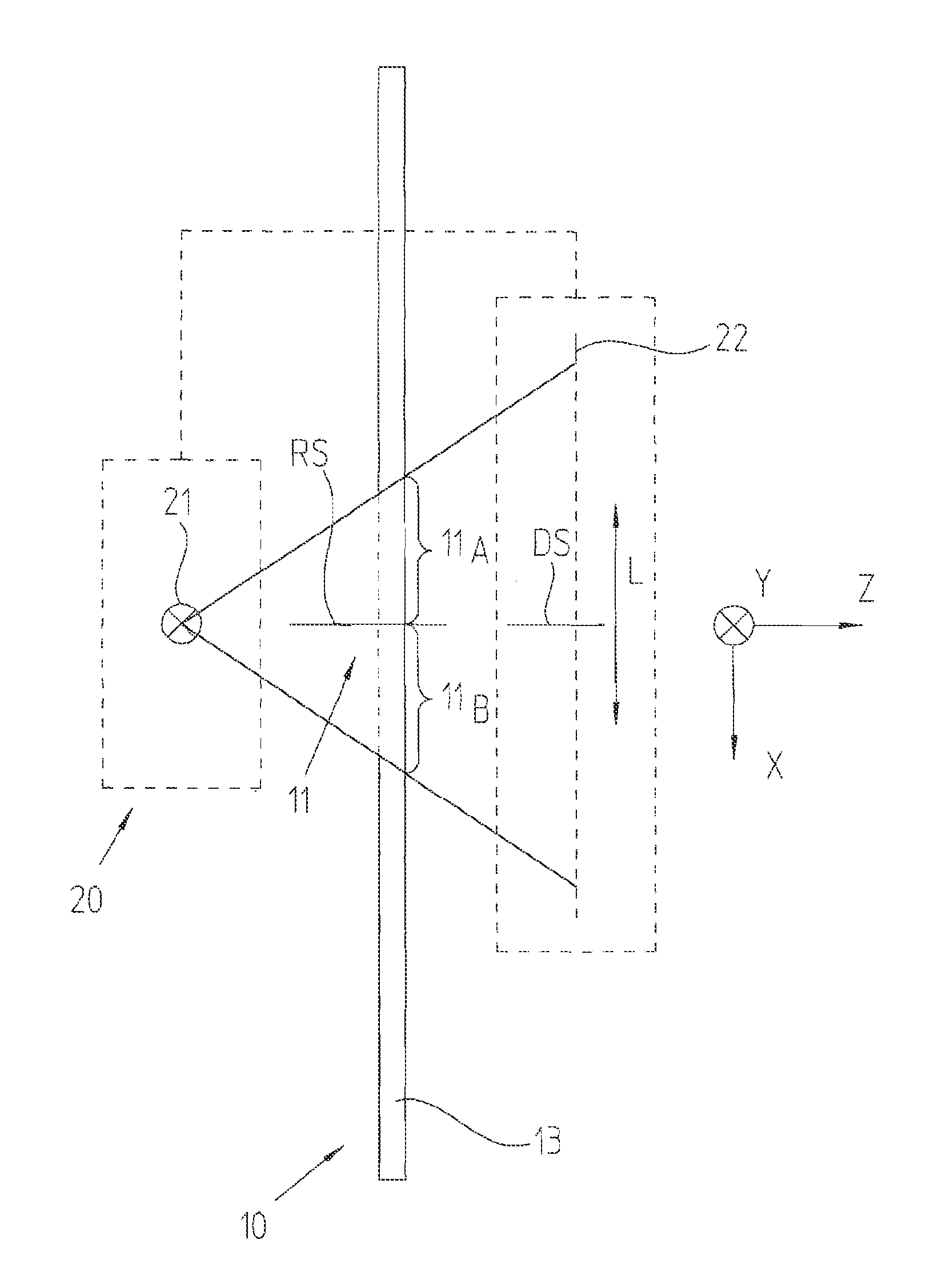
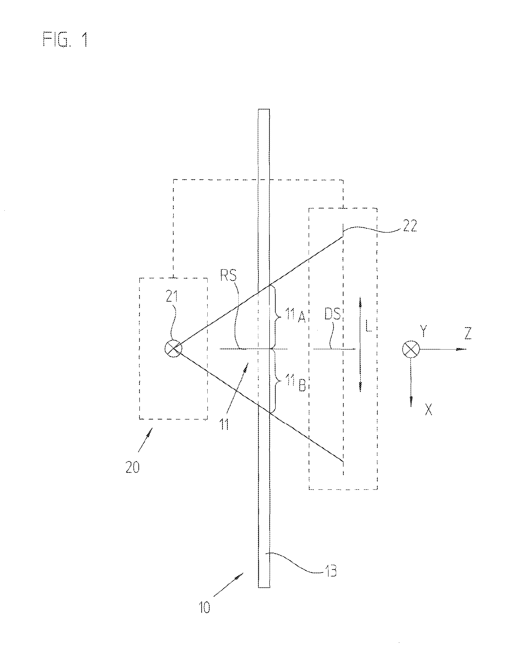
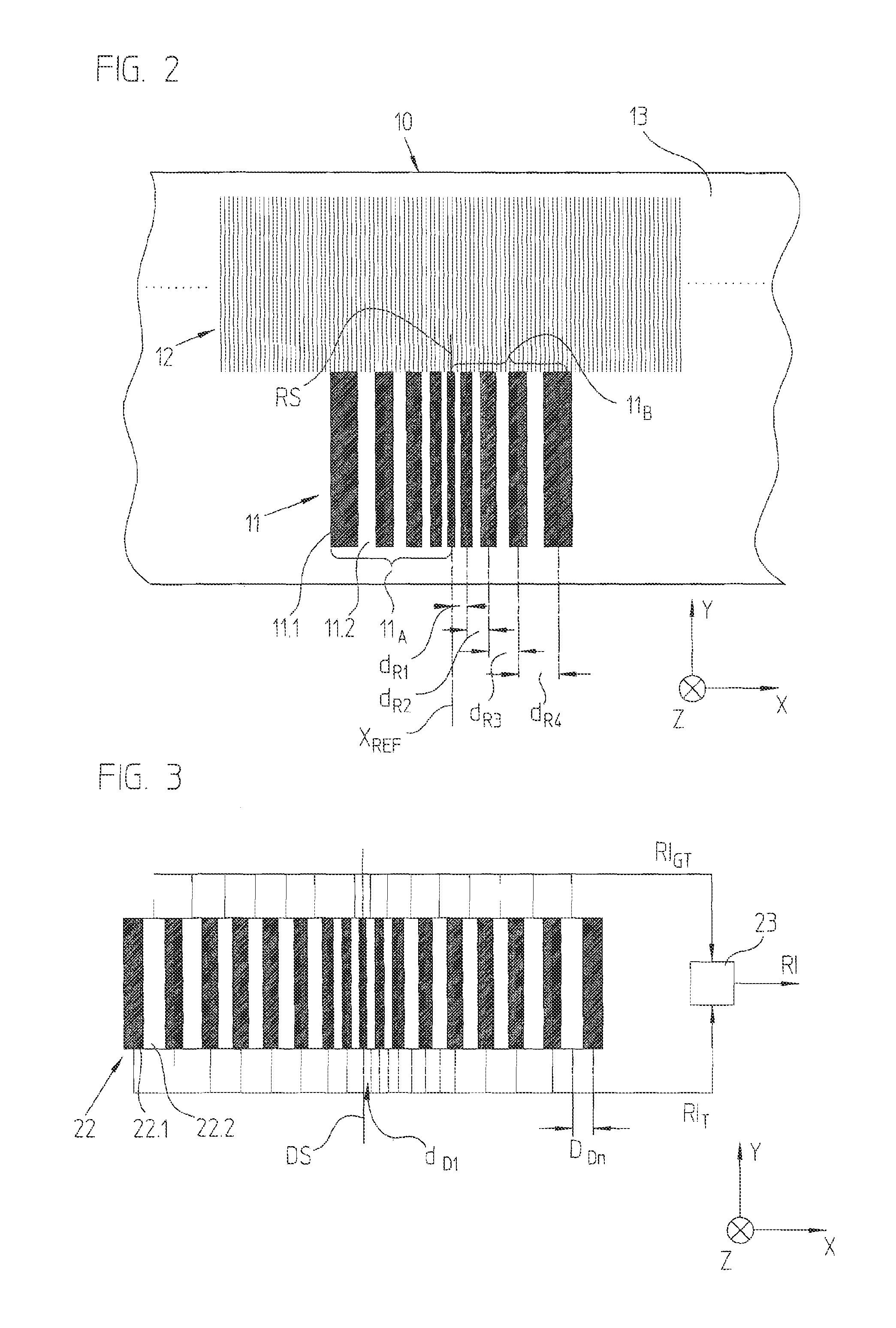
[0037]In the following, an optical position-measuring device according to an example embodiment of the present invention is described in detail with reference to FIGS. 1, 2, 3, as well as 4a-4c. FIG. 1 shows, in highly schematic form, the scanning beam path for generating the reference-pulse signal; FIG. 2 shows a plan view of the measuring standard in the area of the reference marking; FIG. 3 shows a partial view of the detection plane including the interconnection for generating the reference-pulse signals; and FIGS. 4a-4c show various signal patterns in the area of the reference position.
[0038]In the exemplary embodiment shown, the optical position-measuring device takes the form of a transmitted-light linear measuring instrument and includes a scanning unit 20 which is disposed so as to be movable relative to measuring standard 10 in measuring direction x. Measuring standard 10 and scanning unit 20 are joined, for example, to two objects disposed in a manner allowing movement re...
PUM
 Abstract
Description
Claims
Application Information
 - R&D
- Intellectual Property
- Life Sciences
- Materials
- Tech Scout
- Unparalleled Data Quality
- Higher Quality Content
- 60% Fewer Hallucinations
Browse by: Latest US Patents, China's latest patents, Technical Efficacy Thesaurus, Application Domain, Technology Topic, Popular Technical Reports.
© 2025 PatSnap. All rights reserved.Legal|Privacy policy|Modern Slavery Act Transparency Statement|Sitemap|About US| Contact US: help@patsnap.com


