Data card
a data card and data technology, applied in the field of data cards, can solve the problems of increasing the volume of the data card, consuming additional materials, inconvenient to carry, etc., and achieve the effects of reducing volume, reducing volume, and reducing volum
- Summary
- Abstract
- Description
- Claims
- Application Information
AI Technical Summary
Benefits of technology
Problems solved by technology
Method used
Image
Examples
embodiment 1
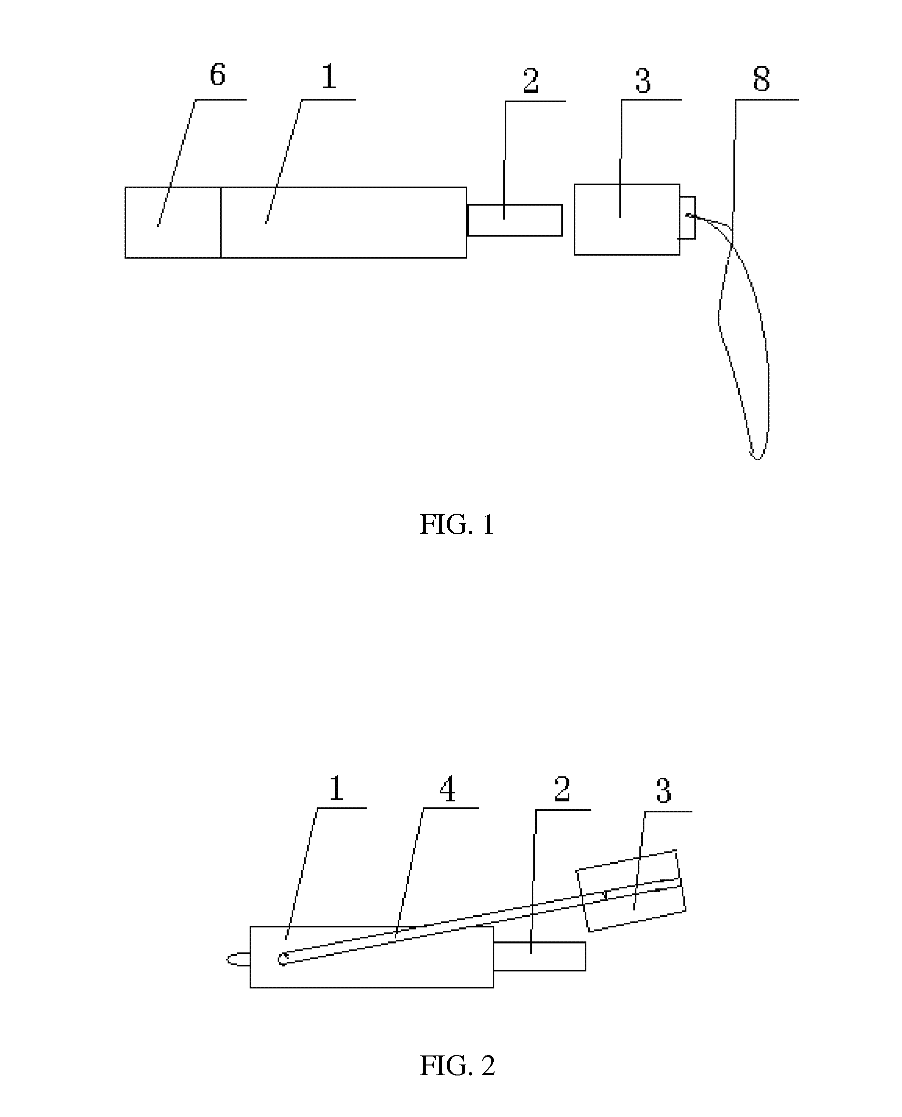
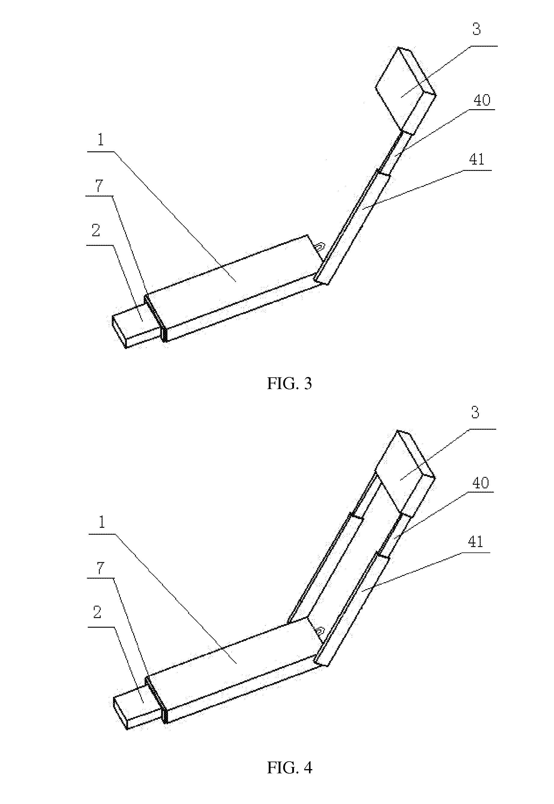
[0023]As shown in FIGS. 2 and 3, the data card of the embodiment of the invention includes a casing 1, provided with a circuit board therein. One end of the casing 1 is provided with a plug 2 electrically connected with the circuit board. The data card of the embodiment of the invention further includes a connecting part 4 and a cap part 3.
[0024]One end of the connecting part 4 is connected with the casing 1, while the other end is connected with the cap part 3. The cap part 3 can cover the plug 2. An antenna which is electrically connected with the circuit board is provided on the connecting part 4 and / or the cap part 3.
[0025]In the embodiment of the invention, the antenna may be electrically connected to the circuit board in various manners, for example, through the connecting part 4 and / or the cap part 3, or through the combination of the cap part 3 and a wire. It is understood that the connecting part 4 may employ a wire. The cap part 3 can cover the plug 2 by insertion, socket,...
embodiment 2
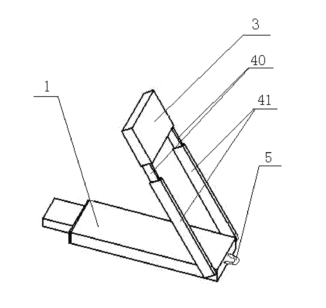
[0033]Shown in FIG. 9 is another embodiment of the invention, which differs from embodiment 1 in that, in this embodiment, the connecting part 4 includes the guide rail 41 and the guide rod 40, one end of the guide rod 40 is movably connected with the casing 1, the other end of the guide rod 40 is connected with one end of the guide rail 41 in socket or insertion connection, and the other end of the guide rail 41 is connected with a cap part 3. Therefore, the cap part 3 can slide along the guide rod 40 to cover the plug 2.
[0034]In this embodiment, the position of the guide rail 41 and the guide rod 40 can be adjusted by sliding the cap part 3 along the guide rod 40 or by means of the guide rod 40 and the movable joint, thereby the antenna can be adjusted to an orientation and a position at which the antenna gain is higher and the signal receiving effect is better.
embodiment 3
[0035]FIG. 10 shows embodiment 3 of the invention, which differs from embodiment 1 in that, in this embodiment, the connecting part 4 is a pivot shaft, the cap part 3 is pivotally connected to a casing 1 through the pivot shaft, and the cap part 3 rotates about the pivot shaft to cover the plug 2. In this embodiment, the main antenna is arranged in the cap part 3, and the diversity antenna is arranged on the pivot. It is understood that the diversity antenna can be arranged on the circuit board or the casing 1. The antenna can be adjusted to an orientation and a position at which the antenna gain is higher and signal receiving effect is better by rotating the cap part 3.
PUM
 Abstract
Description
Claims
Application Information
 - R&D
- Intellectual Property
- Life Sciences
- Materials
- Tech Scout
- Unparalleled Data Quality
- Higher Quality Content
- 60% Fewer Hallucinations
Browse by: Latest US Patents, China's latest patents, Technical Efficacy Thesaurus, Application Domain, Technology Topic, Popular Technical Reports.
© 2025 PatSnap. All rights reserved.Legal|Privacy policy|Modern Slavery Act Transparency Statement|Sitemap|About US| Contact US: help@patsnap.com


