Volume imaging for hydraulic fracture characterization

a hydraulic fracture and volume imaging technology, applied in seismology for waterlogging, instruments, borehole/well accessories, etc., can solve the problems of fracturing treatment not always supporting the concept of the creation of the commonly accepted bi-wing tensile fracture, patterns that have significant consequences for the design of fracturing treatment, and the inability to produce reservoirs without stimulation

Inactive Publication Date: 2011-08-04
SCHLUMBERGER TECH CORP
View PDF6 Cites 69 Cited by
  • Summary
  • Abstract
  • Description
  • Claims
  • Application Information

AI Technical Summary

Benefits of technology

According to some embodiments a method of measuring effects of a hydraulic fracturing process on a subterranean formation surrounding a borehole is provided. The method includes deploying and activating one or more sources of acoustic energy and one or more seismic receivers at known locations at least one of which is downhole so as to provide a plurality of ray-paths between source and receiver pairs traversing portions of the subterranean formation in the vicinity of the borehole. Data measured from the one or more sources by the one or more receivers is processed so as to generate three-dimensional data ind...

Problems solved by technology

These reservoirs cannot be produced without stimulation.
In these formations, field observations of fracturing treatment do not always support the concept of the creation of the commonly accepted bi-wing tensile fracture.
Complex fracture patterns have significant consequences for the design of the fracturing treatment.
The fracture width of each branch of this complex fracture network is smaller than that of a single fracture, and the conventionally used proppant might not be able to be transported to the entire length of the fracture network.
However, it is not necessarily linked to the enhanced permeability zone.
Fracture complexity creates pinch points which restrict proppant transport.
Use of low viscosity fluid with poor transport properties compounds the problem of poor proppant placement.
It is also not clear whether unpropped fracture can be conductive, especially if the amount of shear along the fracture plane is limited.
Ways to properly evaluate the efficiency of the stimulation treatment are lacking and consequently may not be optimized.
This analysis provides very general information about fracture length, fracture conductivity and fracture width when the fractur...

Method used


Image

  • Volume imaging for hydraulic fracture characterization
  • Volume imaging for hydraulic fracture characterization
  • Volume imaging for hydraulic fracture characterization

Examples


Embodiment Construction

The following description provides exemplary embodiments only, and is not intended to limit the scope, applicability, or configuration of the disclosure. Rather, the following description of the exemplary embodiments will provide those skilled in the art with an enabling description for implementing one or more exemplary embodiments. It being understood that various changes may be made in the function and arrangement of elements without departing from the spirit and scope of the invention as set forth in the appended claims.

Specific details are given in the following description to provide a thorough understanding of the embodiments. However, it will be understood by one of ordinary skill in the art that the embodiments may be practiced without these specific details. For example, systems, processes, and other elements in the invention may be shown as components in block diagram form in order not to obscure the embodiments in unnecessary detail. In other instances, well-known proces...


PUM


Abstract

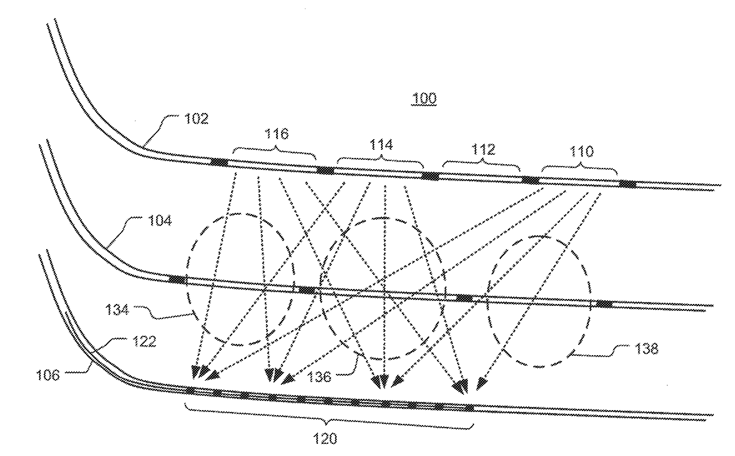
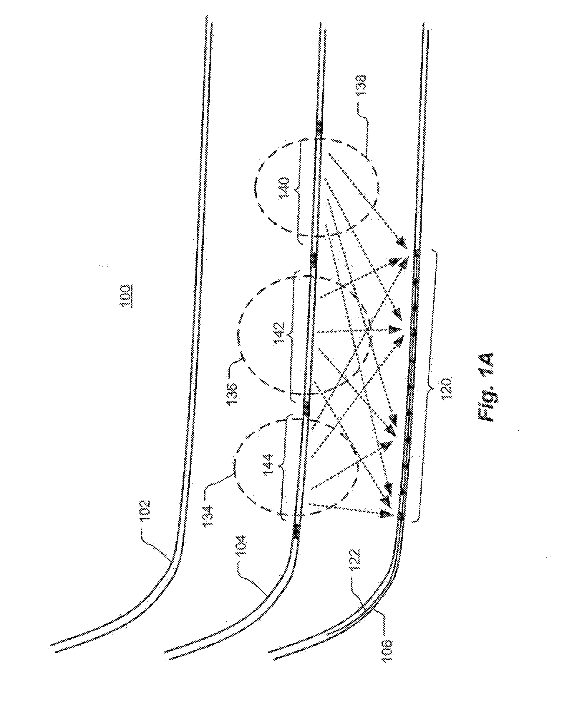
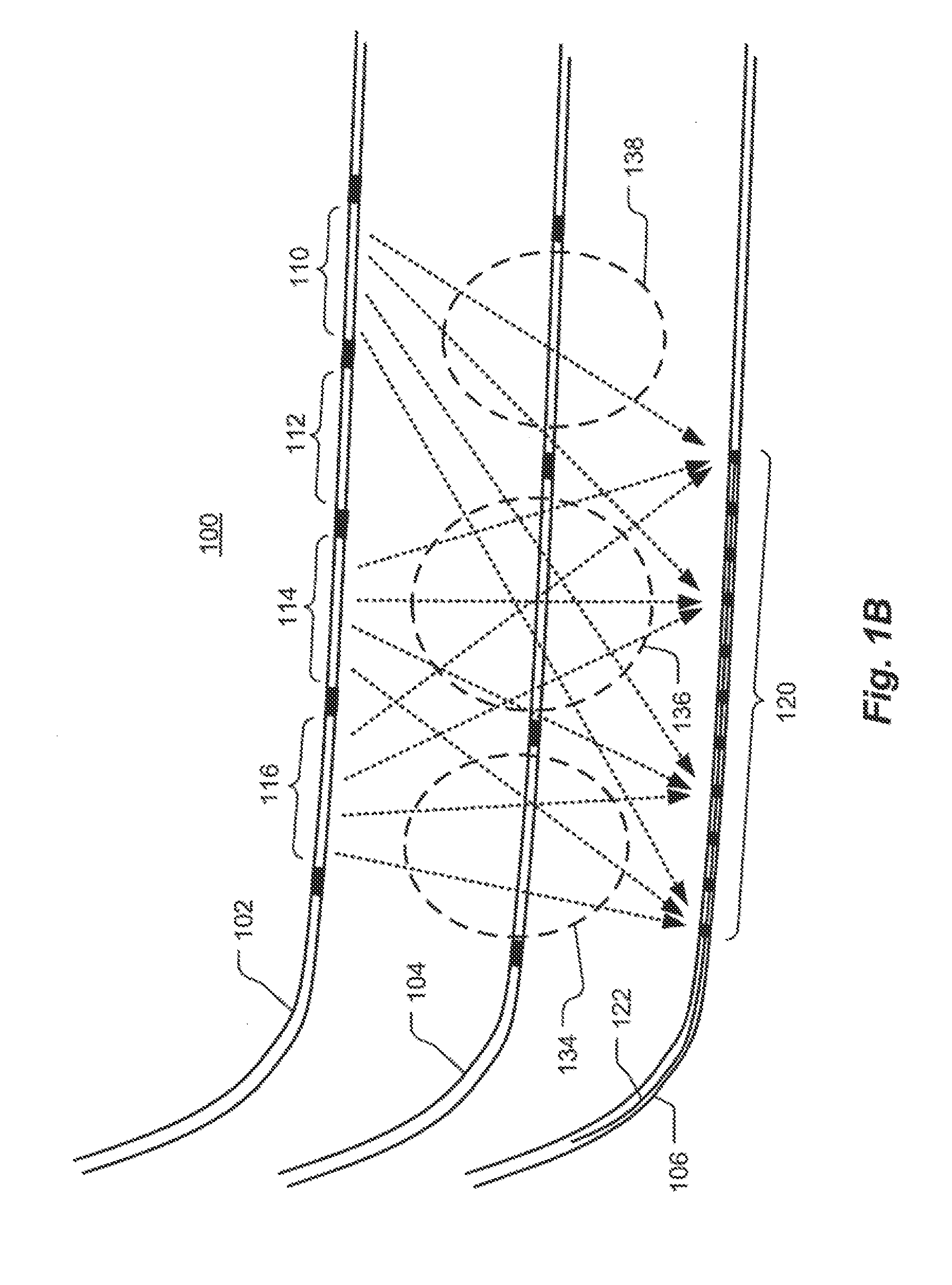
Methods and systems are described for measuring effects of a hydraulic fracturing process. The techniques can utilizes cross-well seismic technology, such as used in Schlumberger's DeepLook-CS tools and service, or in some case surface to borehole or borehole to surface seismic technology. The downhole seismic sources at known locations can be conventional sources or can be other types of equipment operating at known locations such as perforation guns. The source is activated or swept creating energy which is transmitted through the formation. The energy is recorded at the receiver array and processed to yield a tomographic image indicating changes in the subterranean formation resulting from the hydraulic fracturing process. The process can be performed pre and post hydraulic fracture stimulation to generate a difference image of propped fractures in the reservoir.

Description

BACKGROUND1. FieldThis patent specification relates generally to hydraulic fracturing characterization in wellbore applications. More particularly, this patent specification relates to three-dimensional imaging for hydraulic fracture characterization.2. BackgroundHydraulic fracturing for stimulation of conventional reservoirs consists of the injection of a high viscosity fracturing fluid at high flow rate to open and then propagate a bi-wing tensile fracture in the formation. With the exception of the near-wellbore region where a complex state of stress might develop, it is expected that this fracture will propagate normal to the far-field least compressive stress. The length of this tensile fracture can attain several hundred meters during a fracturing treatment of several hours. The fracturing fluid contains proppants, which are well-sorted small particles which are added to the fluid to maintain the fracture open once the pumping is stopped and pressure is released. This allows o...

Claims


Application Information

Patent Timeline
IPC IPC(8): G01V1/00
CPCG01V1/00E21B43/26G01V1/42G01V1/288G01V2210/646G01V2210/1234
Inventor THIERCELIN, MARCLE CALVEZ, JOELDURRANI, JAVAIDMCCALLUM, MARKMARION, BRUCE P.WILKENS, LUKETHIERCELIN, GISELE
Owner SCHLUMBERGER TECH CORP
Why Eureka
Try Eureka