
WLAN apparatus

a wireless communication and wlan technology, applied in the field of wireless communications, can solve the problems of limiting the improvement of the throughput of the wireless communication network, the ieee 802.11a communication distance is shorter than the ieee 802.11b, and the ieee 802.11n medium access control/physical layer protocol is not effective in providing a throughput of 1 gbps or more, so as to achieve the effect of high throughput and extension of the servi

Active Publication Date: 2011-08-04
LG ELECTRONICS INC
View PDF6 Cites 29 Cited by
  • Summary
  • Abstract
  • Description
  • Claims
  • Application Information

AI Technical Summary

Benefits of technology

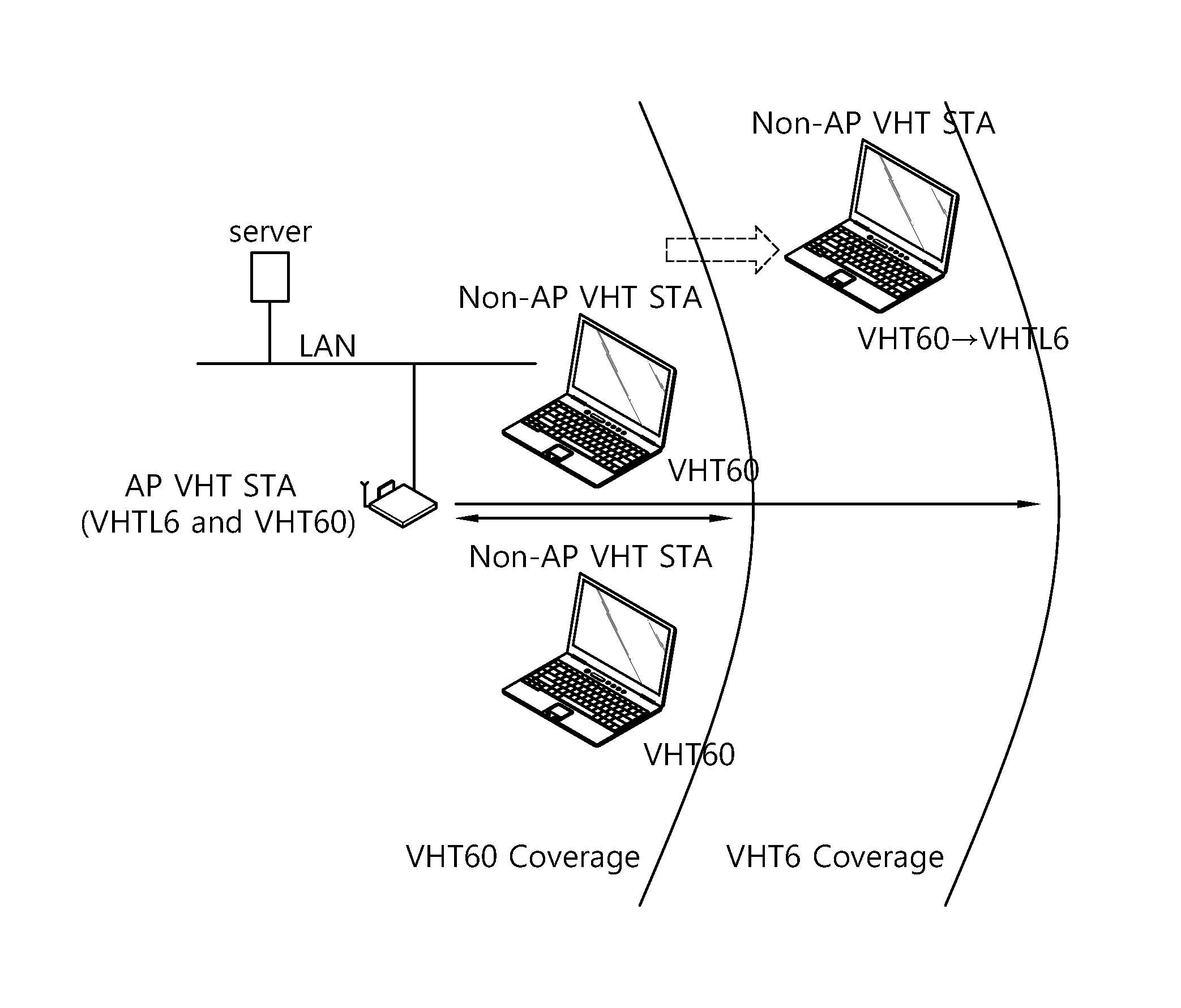
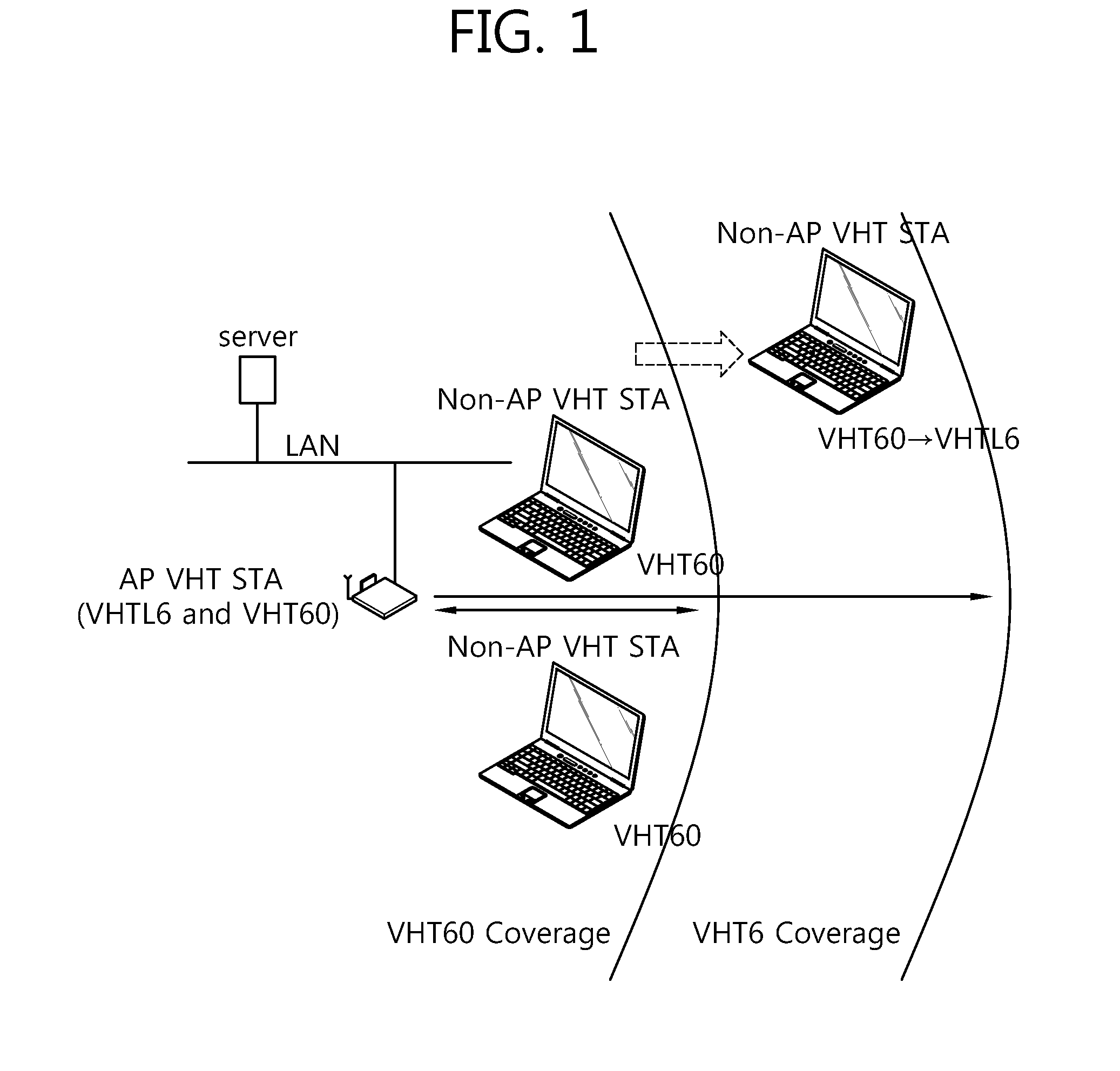
[0014]The present invention provides protocol architecture for an overlay WLAN, a frame format for the same, and a transmitting method thereof, in which the efficiency of the overlay WLAN is enhanced by extending 60 GHz-channel service coverage in a VHT WLAN system.
[0023]In a WLAN system, it is possible to extend service coverage of a basic service set (BSS) using a band of 60 GHz. Further, non-AP STAs located near to one another form an independent BSS (IBSS) so that they can communicate using a band of 60 GHz to thereby achieve a high throughput, and communicate with a relatively distant AP VHT STA using a band of 6 GHz through a millimeter (mm) portal to thereby interwork with an external network.

Problems solved by technology

However, it is disadvantageous that IEEE 802.11a has a shorter communication distance than IEEE 802.11b.
However, an IEEE 802.11n medium access control (MAC) / physical layer (PHY) protocol is not effective in providing a throughput of 1 Gbps or more.
In conclusion, there is a limit to improvement in the throughput of the wireless communication network while keeping the existing IEEE 802.11n MAC / PHY protocol having the single STA architecture, intact.
The channel or less then 6 GHz shows relatively broad service coverage, but has a disadvantage that an available channel bandwidth is small.
However, since the non-AP VHT STA has only a single-radio interface, it cannot support both the channel of less than 6 GHz and the channel of 60 GHz.
Thus, if the non-AP VHT STA is located outside the VHT60 coverage, it is difficult to achieve the high throughput since the non-AP VHT STA cannot use the channel band of 60 GHz in communicating with the AP VHT STA.
This causes the AP VHT STAs to inevitably use the channel band of less than 6 GHz even though the non-AP VHT STAs are located within the VHTL6 coverage and capable of communicating with each other through the channel band of 60 GHz in the ad-hoc mode, thereby lowering the efficiency of the overlay WLAN in the VHT WLAN system.

Method used


Image

  • WLAN apparatus
  • WLAN apparatus
  • WLAN apparatus

Examples


Embodiment Construction

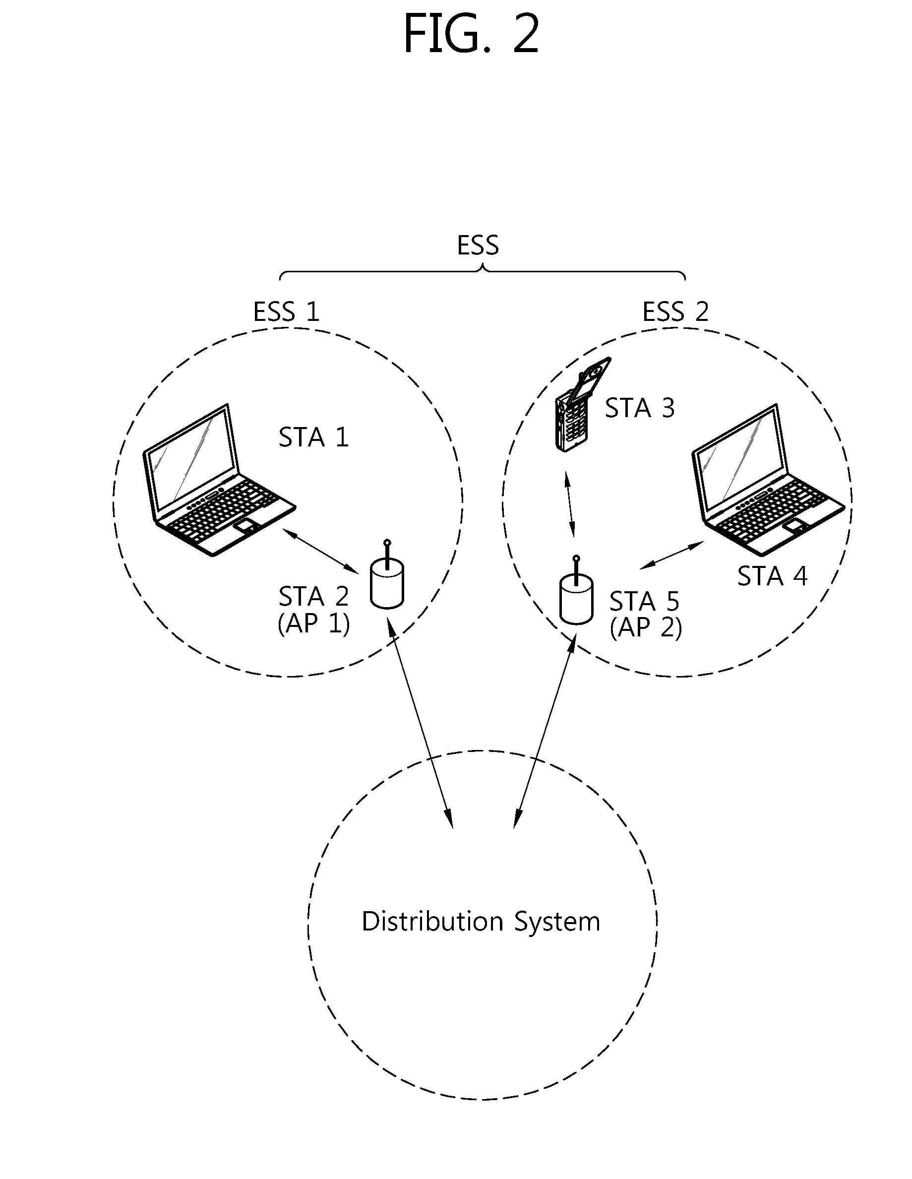
[0034]FIG. 2 schematically illustrates a configuration of an example of a very high throughput (VHT) wireless local area network (WLAN) system to which an exemplary embodiment of the present invention can be applied.

[0035]Referring to FIG. 2, a WLAN system such as the VHT WLAN system includes one or more basis service sets (BSS). The BSS is a set of stations (STA) which are successfully synchronized and capable of communicating with one another, and does not mean a specific region. In a medium access control (MAC) service access point (SAP) like the WLAN system to which an exemplary embodiment of the present invention can be applied, the BSS supporting an ultrahigh data processing rate of 1 GHz or higher will be called a very high throughput (VHT) BSS.

[0036]Further, the VHT BSS is divided into an infrastructure BSS and an independent BSS (IBSS). FIG. 2 illustrates the infrastructure BSS. The infrastructure BSS (BSS1, BSS2) includes one or more non-AP STA (non-AP STA1, non-AP STA3 an...


PUM


Abstract

A wireless local area network (WLAN) apparatus for a WLAN system includes a first medium access protocol (MAC) entity which supports a first frequency band; and a second MAC entity which supports a second frequency band, wherein a MAC management frame for the first frequency band is encapsulated in a MAC management frame for the second frequency band, and transmitted through the second frequency band.

Description

TECHNICAL FIELD[0001]The present invention relates to wireless communications, and more particularly, to a wireless local area network (WLAN) apparatus supporting a multi-band and a method using the same.BACKGROUND ART[0002]With the recent development of information communication technology, a variety of wireless communication technology has been developed. A WLAN is the technology permitting wireless access to Internet in home or companies or specific service areas by the use of portable terminals such as a personal digital assistant (PDA), a laptop computer, and a portable multimedia player (PMP) on the basis of a radio frequency technology.[0003]The IEEE (Institute of Electrical and Electronics Engineers) 802 which is a standardization of the WLAN technology established in February, 1980 has carried out much standardization work. In the initial WLAN technology, a data rate of 1 to 2 Mbps was supported by the use of frequency hopping, spread spectrum, and infrared communication us...

Claims


Application Information

Patent Timeline
Patent Type & Authority Applications(United States)
IPC IPC(8): H04W88/02
CPCH04W16/26H04W88/06H04W84/12H04B7/2612H04L69/22H04W72/0453
Inventor SEOK, YONG HO
Owner LG ELECTRONICS INC
Learn More