Hydraulically Damping Bushing Bearing

a technology of elastomeric bushing bearings and bearings, which is applied in the direction of elastic bearings, bearing units rigid support, shock absorbers, etc., can solve the problems of inability to reliably predict the damping characteristic of bearings with large cardanic loads, the geometry of the damping means channel is disadvantageously not clearly defined, and the conventional elastomeric bushing bearings cannot withstand a limited thermal load

Inactive Publication Date: 2011-08-04
ZF FRIEDRICHSHAFEN AG
View PDF8 Cites 45 Cited by
  • Summary
  • Abstract
  • Description
  • Claims
  • Application Information

AI Technical Summary

Benefits of technology

[0011]It is therefore an object of the invention to provide an elastomeric bushing bearing with hydraulic damping which eliminates the aforementioned problems.
[0016]In a particularly preferred embodiment of the bushing bearing according to the invention, the elastic portion of the end segments arranged between the rigid inner ring and the rigid outer ring is made of an elastomer which is more temperature-stable than the other parts of the elastomeric bearing body arranged on the center main segment. In this way, thermally very robust bushing bearings can be realized, without limiting the damping comfort of the bearing and its long-term performance. This would not be possible if the entire bearing body were made of a highly temperature-stabile elastomer, because it has been observed that particularly temperature-stabile elastomers disadvantageously have inferior long-term performance when subjected to mechanical loads. When the bearings are exposed to high temperatures, their elastomeric components experience increased wear due to the thermal stress, which may cause premature failure in particular in the region of mechanically highly stressed expanding walls of the chambers. It has been observed that at high temperatures the elastomer has a tendency to become brittle and to finally crumble, causing leaks in the region of the expanding walls. However, with the segmented construction of the inner bearing part of the bushing bearing according to the invention and by using a more temperature-robust elastomer for the end segments, the end segments can withstand the stress at high temperatures in the region of the expanding walls, thereby improving the long-term performance under mechanical stress compared to the more temperature-robust elastomers. With respect to the more temperature-robust construction of the expanding walls, a silicone-rubber-mixture can be used for the elastomeric elements of the end segments. Particularly advantageously, an ethylene-propylene-diene mixture (EPDM) can be used for these elastomeric elements.
[0017]According to a particularly preferred embodiment, the channel support element of the bushing bearing according to the invention is made of plastic. Plastic can be used for the channel support because the channel support is pushed onto the outside of the bearing body between the bearing body and the outer sleeve. This avoids problems associated with the vulcanization of conventional channel support elements made of plastic, which are vulcanized into the bearing body while being freely held during the vulcanization process inside the mold in the region to be filled with elastomer for the bearing body. In addition, channel support elements made of plastic can be manufactured at much lower costs than the conventional so-called aluminum channel cages which are also vulcanized in the bearing body. In addition, the use of plastic advantageously reduces the weight. Moreover, the bearing can be much more easily tuned with the exterior channel support element made of plastic due to the intentional pretension of the elastomeric bearing body. A separate calibration process for producing the pretension in the elastomeric bearing body, where the diameter of the outer sleeve is reduced, can be eliminated, because the elastomer is already pretensioned, due to the compliance of the plastic, when the inner bearing body, which is surrounded by the channel support element and connected by vulcanization, is pressed into the outer sleeve. By moving the channel from the interior of the bearing body into a channel support element arranged between the bearing body and the outer sleeve, the increased available space offers more possibilities for the geometric design of the channel. Particularly advantageously, mass damping channels with a large channel length can be realized. For example, the channel according to a particular embodiment of the invention extends over the entire axial length of the channel support element. It terminates in the corresponding chamber at a respective end face of the channel support element in the region of the transition between the main segment and the respective end segments of the inner bearing part.
[0019]Because the radial stops, unlike with conventional bearings, are not implemented on the axial ends of the bearing with corresponding clips, but are instead disposed inside the bearing, namely in the chambers, significantly more space is available for their design. According to a preferred embodiment, the radial stops, which are formed from the elastomer of the bearing body, extend inside the chambers on the outside of the aforementioned outer bearing core made of plastic over the entire axial length of the outer bearing core. The bushing bearing formed in this way can advantageously absorb high cardanic loads and large cardanic angles, respectively.
[0020]With the segmented structure of the inner bearing part, the functions in the bearing of the invention are separated such that static loads are absorbed by the elastomer of the center main segment, whereas the hydraulic function is provided by the expanding walls of the separate end segments. Advantageously, the ribs of the center main segment can be designed to be rather wide because the channel is moved into the outer bearing region or into the channel support element arranged outside the bearing party, respectively, and therefore constructed to be very durable with respect to the absorbed static loads, while simultaneously the thickness of the material for the expanding walls and their curvature can be varied over a wide range because these are formed in the end segments. An improved dynamic characteristic of the bearing and an improved performance of Cstatic to Cdynamic can be attained with thinner expanding walls due to the improved compliance.

Problems solved by technology

In particular with bearings having a radially operating hydraulic damping system, the chambers extending in the bearing and the damping means channel frequently limiting the space available for forming corresponding stop elements or stop faces and may hence cause problems.
In addition, the comparatively small stop elements or stop faces in the clips may create problems by limiting loading by cardanic operating forces acting on radially damping bushing bearings.
By eliminating a channel support element and constructing the channel walls from the elastomer of the bearing body and the caps, respectively, the geometry of the damping means channel is disadvantageously not clearly defined.
This is disadvantageous in particular with cardanic loads of the bearing, because the bearing's damping characteristic for large cardanic loads cannot be reliably predicted due to the accompanying changes in the channel geometry.
It has also been observed that conventional elastomeric bushing bearings can only withstand a limited thermal load.
When used in automobiles, increased wear occurs on the bearings in regions with a very hot climate.
Due to the high temperatures, the elastomer of the bearing body frequently becomes brittle.
If these bearings are used for hydraulic damping, leaks may occur in the region of the bearings, causing the bearing to fail under adverse conditions where it does not provide the intended damping effect.

Method used


Image

  • Hydraulically Damping Bushing Bearing
  • Hydraulically Damping Bushing Bearing
  • Hydraulically Damping Bushing Bearing

Examples


Embodiment Construction

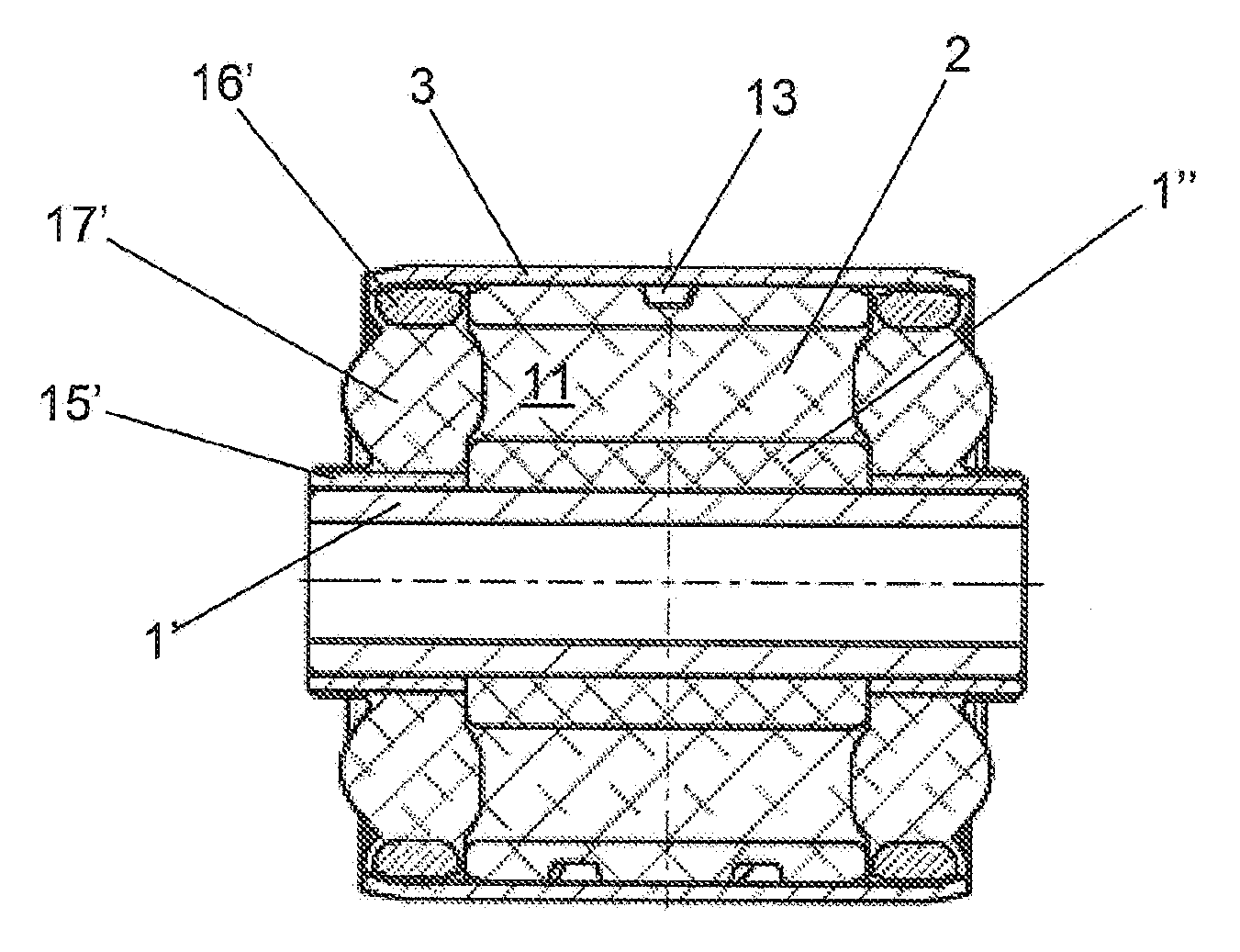
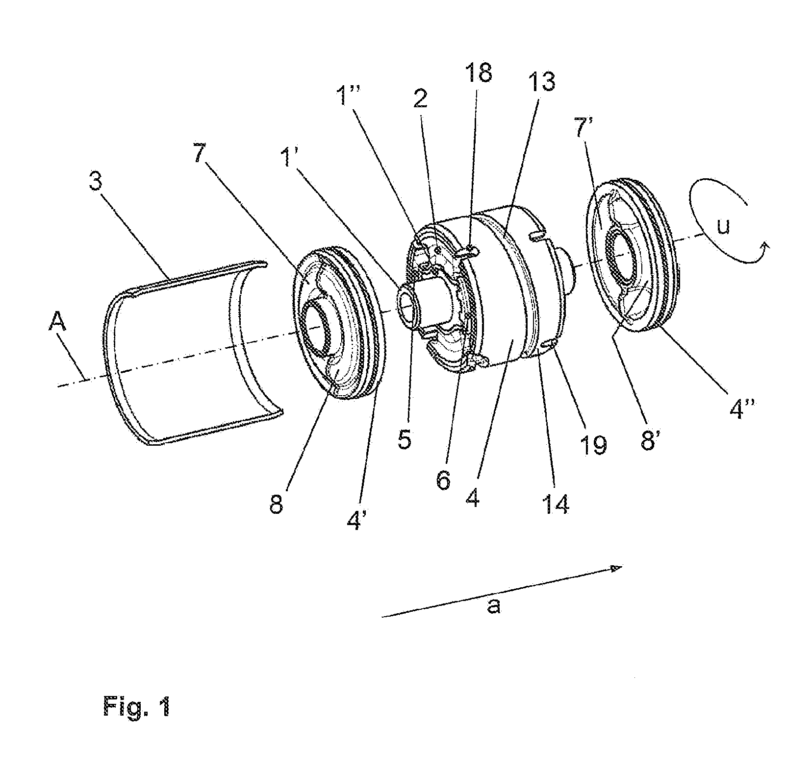
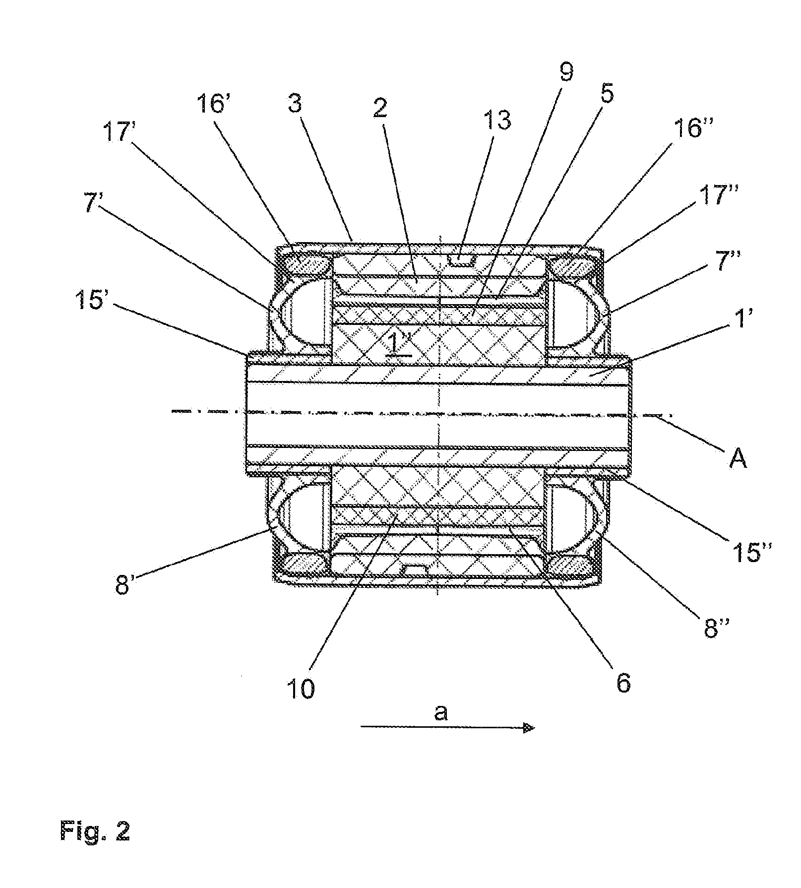
[0027]FIG. 1 shows a possible embodiment of the bushing bearing according to the invention in a three-dimensional view. The bearing is shown in the Figure in an exploded view. It is composed of an inner bearing part 4, 4′, 4″ and an outer sleeve 3 receiving the inner bearing part 4, 4′, 4″, wherein the outer sleeve 3 is shown in the diagram with a cut-out circumferential segment. The inner bearing part 4, 4′, 4″ is constructed in segments with respect to the longitudinal axis A of the bearing. It consists of the center main segment 4 with the bearing core 1′, 1″ and the elastomeric bearing body 2, which is connected with the bearing core 1′, 1″ through vulcanization and in which the chambers 5, 6 for the damping means are formed. The outside of the chambers is axially delimited by the two end segments 4′, 4″ with the expanding walls 7′, 7″, 8′, 8″ formed thereon. The end segments 4′, 4″ (see FIG. 2) consist of a rigid inner ring 15′, 15″, a rigid outer ring 16′, 16″ and an elastic o...


PUM


Abstract

Chambers for a bushing bearing with damping means include outer sleeve and inner bearing part, accommodated in the outer sleeve with rigid bearing core and elastomeric bearing body surrounding the core. The expanding walls of the chambers are disposed transversely to the bearing axis (A). The inner bearing part is segmented with respect to the longitudinal axis (A) of the bearing and includes a center main segment with bearing core and bearing body and two end segments, each having an inner ring, an outer ring, and an interposed elastomeric element forming expanding wall of a chamber. The end segments are pressed with inner ring onto axial ends of the bearing core so that the material overlaps between the elastomeric elements of the end segments and the ribs of the bearing body. The channel is formed outside of the bearing body in a channel carrier element.

Description

[0001]This is an application filed under 35 USC §371 of PCT / DE2009 / 050038, claiming priority to DE 10 2008 040 548.5 filed on Jul. 18, 2008.BACKGROUND OF THE INVENTION[0002](1) Field of the Invention[0003]The invention relates to an elastomeric bushing bearing with hydraulic damping. The invention more particularly relates to a bushing bearing with a special configuration which makes it possible to realize a bushing bearing which is thermally very robust.[0004](2) Description of Related Art[0005]Elastomeric bushing bearings of a type employed in large numbers particularly in the construction of vehicles consist essentially of a metallic, mostly rotationally symmetric and frequently cylindrical bearing core, an outer sleeve which surrounds the bearing core and is generally also made of metal, and an elastomeric bearing body arranged between the bearing core and the outer sleeve and forming an elastomeric support spring. The elastomeric bearing body is generally connected by vulcaniza...

Claims


Application Information

Patent Timeline
Patent Type & Authority Applications(United States)
IPC IPC(8): F16C27/00
CPCF16F13/14
Inventor ESCHWEILER, JOSEFGROSS, JOSEF PETER
Owner ZF FRIEDRICHSHAFEN AG
Why Eureka
Try Eureka