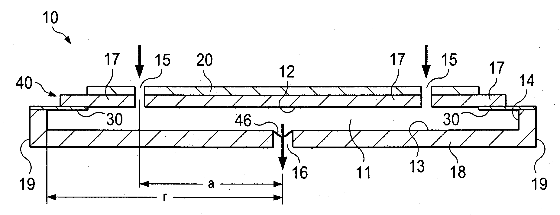
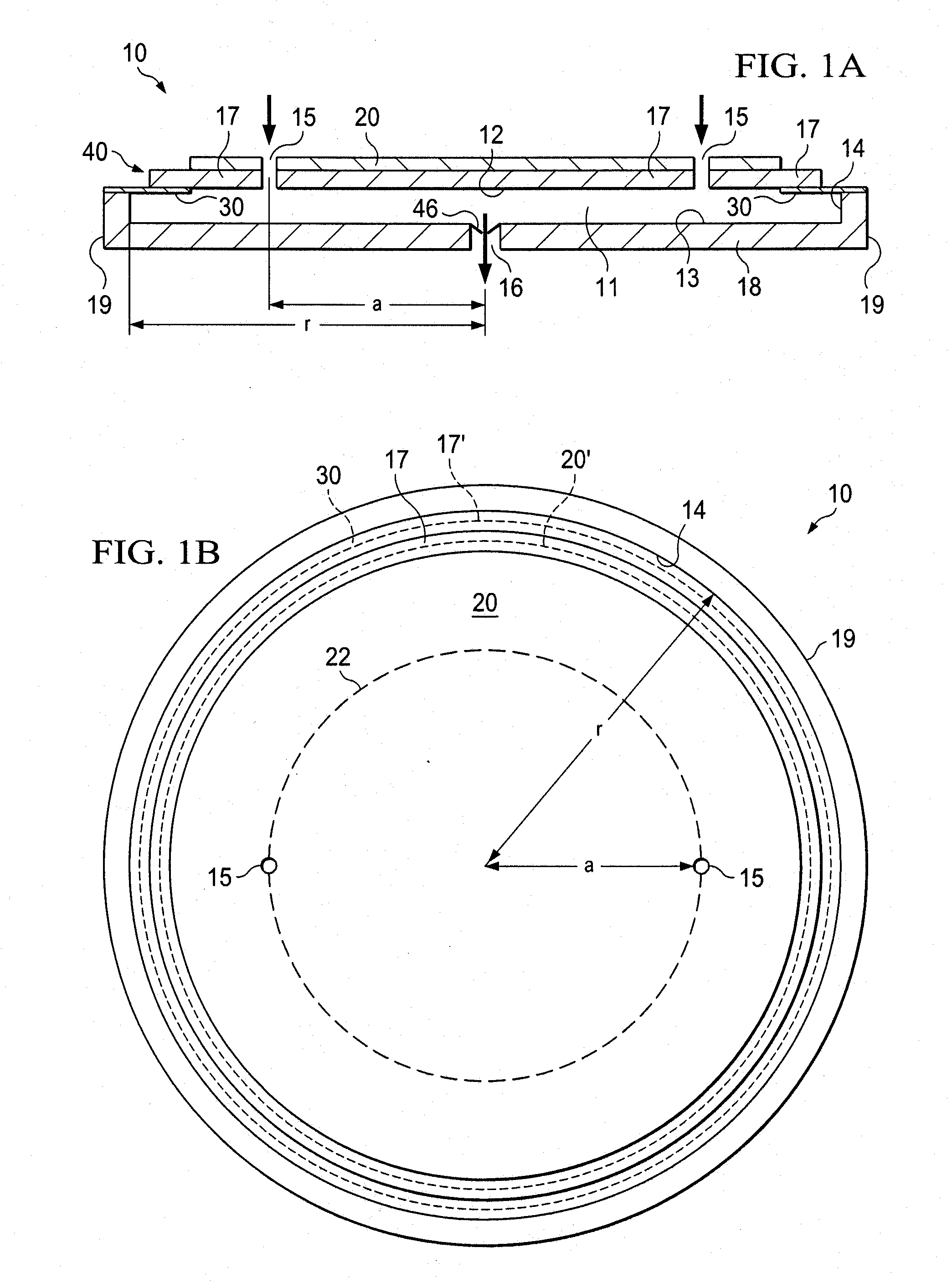
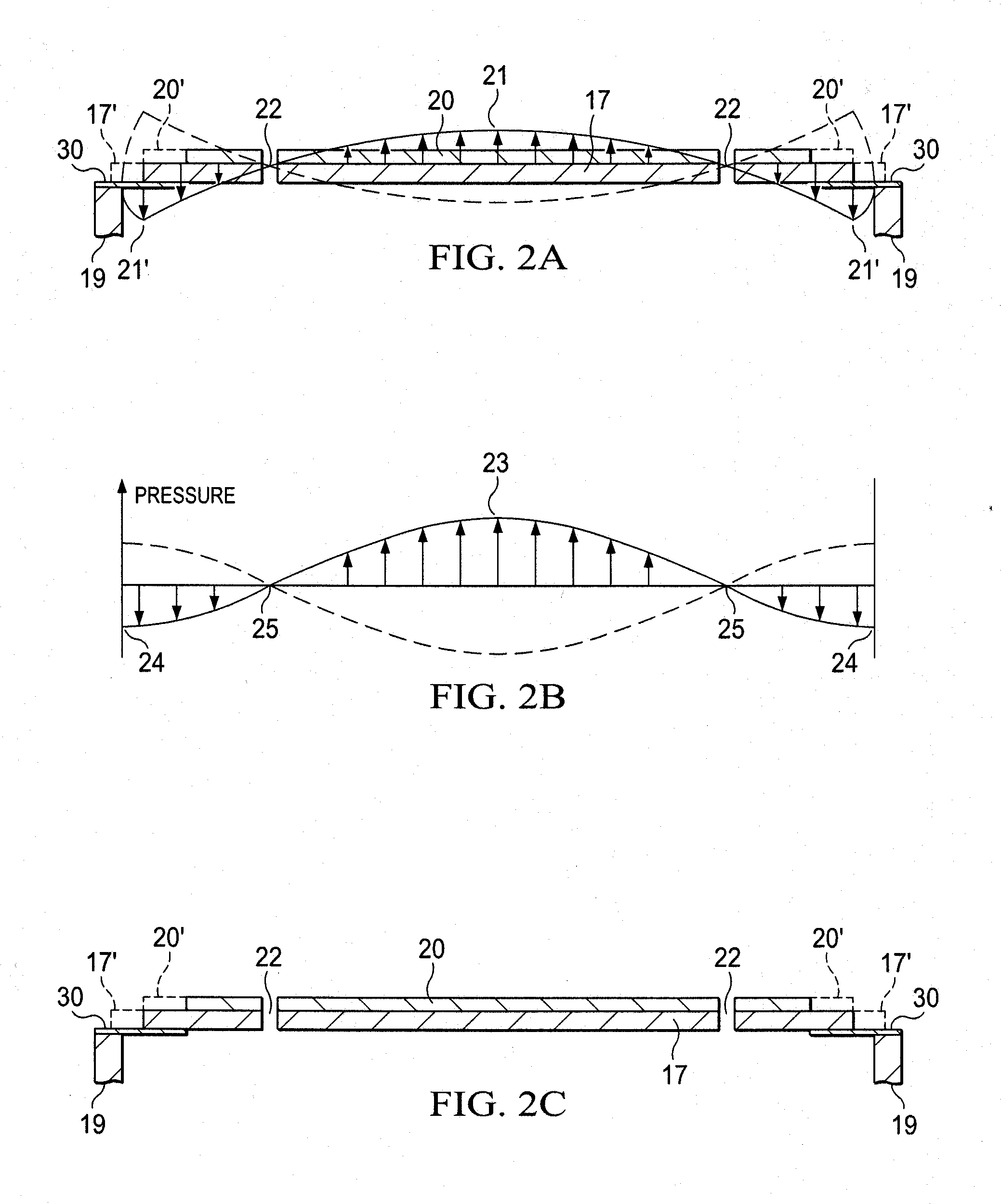
Fluid disc pump with square-wave driver

a technology of square wave and pump, which is applied in the field of pumping fluid, can solve the problems of increasing power consumption, reducing the performance of the actuator and, consequently, the pump, and not using high-amplitude acoustic resonance in the disc-shaped cavity, and achieving the effect of reducing the efficiency of the pump

Active Publication Date: 2011-08-04
KCI LICENSING INC
View PDF6 Cites 48 Cited by
  • Summary
  • Abstract
  • Description
  • Claims
  • Application Information

AI Technical Summary

Benefits of technology

[0012]According to the principles of the present invention, the pump further comprises a drive circuit having an output that drives the piezoelectric component of the actuator primarily at the fundamental frequency. The drive signal is a square-wave signal and the drive circuit eliminates or attenuates certain harmonic frequencies of the square-wave si...

Problems solved by technology

However, high amplitude acoustic resonance has not been employed within disc-shaped cavities in which radial pressure oscillations are excited until recently.
A problem encountered when utilizing a square-wave as the drive signal for such actuators is that a square wave contains additional frequencies at multiples of its fundamental frequency (f), i.e., harmonic frequencies, that can coincide with, or be sufficiently close to, higher-frequency resonant frequencies of the actuator associated with other oscillatory modes (e.g. higher order “bending” modes or radial “breathi...

Method used


Image

  • Fluid disc pump with square-wave driver
  • Fluid disc pump with square-wave driver
  • Fluid disc pump with square-wave driver

Examples


first embodiment

[0053]the solution is to add a electrical filter in series with the actuator 40 to eliminate or attenuate the amplitude of the seventh harmonic 377 present in the square-wave drive signal. For example, a series inductor may be used as a low-pass filter to attenuate the high-frequency harmonics in the square-wave drive signal, effectively smoothing the square-wave output of the drive circuit. Such an inductor adds an impedance Z in series with the actuator, where |Z|=2πfL. Here f is the frequency in question, and L is the inductance of the inductor. For |Z| to be greater than 300Ω at a frequency f=147 kHz, the inductor should have a value greater than 320 μH. Adding such an inductor significantly thereby increases the impedance of the actuator 40 at 147 kHz. Alternative low-pass filter configurations, including both analog and digital low-pass filters, may be utilized in accordance with the principles of the present invention. Alternative to a low-pass filter, a notch filter may be u...

second embodiment

[0054]In a second embodiment, the PWM square-wave signal 370 can be modified to reduce the amplitude of the seventh harmonic 377 by modifying the duty-cycle of the PWM square-wave signal 370. A Fourier analysis of the PWM square-wave signal 370 can be used to determine a duty-cycle that results in reduction or elimination of the amplitude of the seventh harmonic of the drive frequency as indicated by Equation 1.

An=2T∫0TSin(2nπ·tT)f(t)t[Equation1]

Here An is the amplitude of the nth harmonic, t is time, and T is the period of the square wave. The function ƒ(t) represents the PWM square wave signal 370, taking a value of −1 for the “negative” part of the square wave, and +1 for the “positive” part. The function ƒ(t) clearly changes as the duty cycle is varied.

[0055]Solving Equation 1 for the optimal duty-cycle to eliminate the seventh harmonic (i.e. setting An=0 for n=7):

A7=2T∫0TSin(14π·tT)t-2T∫T1TSin(14π·tT)t=0∴Cos(7πT1T)=1[Equation2]

In these equations T1 is the time at which the squa...


PUM


Abstract

A pump having a substantially cylindrical shape and defining a cavity formed by a side wall closed at both ends by end walls wherein the cavity contains a fluid is disclosed. The pump further comprises an actuator operatively associated with at least one of the end walls to cause an oscillatory motion of the driven end wall to generate displacement oscillations of the driven end wall within the cavity. The pump further comprises a valve for controlling the flow of fluid through the valve.

Description

BACKGROUND OF THE INVENTION[0001]1. Field of the Invention[0002]The illustrative embodiments of the invention relate generally to a pump for pumping fluid and, more specifically, to a pump having a substantially disc-shaped cavity with substantially circular end walls and a side wall and a valve for controlling the flow of fluid through the pump in conjunction with an electronic circuit for driving a square-wave signal that reduces harmonic excitation of the pump.[0003]2. Description of Related Art[0004]The generation of high amplitude pressure oscillations in closed cavities has received significant attention in the fields of thermo-acoustics and pump type compressors. Recent developments in non-linear acoustics have allowed the generation of pressure waves with higher amplitudes than previously thought possible.[0005]It is known to use acoustic resonance to achieve fluid pumping from defined inlets and outlets. This can be achieved using a cylindrical cavity with an acoustic drive...

Claims


Application Information

Patent Timeline
IPC IPC(8): A61H7/00F04B43/04
CPCF04B43/046F04B43/04
Inventor JAEB, JONATHANPADBURY, CHRISTOPHER JOHN
Owner KCI LICENSING INC
Why Eureka
Try Eureka