Dielectric Jaw Insert For Electrosurgical End Effector

Active Publication Date: 2011-08-04
TYCO HEALTHCARE GRP LP
View PDF81 Cites 104 Cited by
  • Summary
  • Abstract
  • Description
  • Claims
  • Application Information

AI Technical Summary

Benefits of technology

The present disclosure relates to an end effector assembly for use with an electrosurgical instrument. The end effector assembly includes a pair of opposing first and second jaw members and a jaw insert. Each of the opposing jaw members has a tissue contacting surface and one or more of the jaw members are monolithic. Additionally, at least one of the jaw members is moveable relative to the other from a first, open position to a second, closed position for grasping tissue. The monolithic jaw member also has a cavity defined therein. The jaw insert is selectively positionable within the cavity of the monolithic jaw member. The jaw insert includes a tissue contacting surface and a portion of the jaw insert includes a dielectric material configured to reduce the thermal mass of the monolithic jaw member.
In embodiments, the jaw insert may define a cutting channel therealong configured to receive a cutting element therealong. The jaw insert may include a portion of conductive material that is configured to conduct electrosurgical energy received from the electrosurgical energy source. The jaw insert may also be overmolded to the monolithic jaw member. In embodiments, the jaw insert may include one or more mechanical interfaces that cooperate with corresponding mechanical interfaces to selectively position the jaw insert within the cavity. The mechanical interfaces may include one or more biasing members.
In embodiments, the tissue contacting surface of the at least one monolithic jaw member and the tissue contacting surface of the jaw insert may be offset relative to one another. Additionally, the

Problems solved by technology

Since the entire depth of the cutting channel is part of the electrical circuit in this type of jaw, material in the blade slot may become subject to the electrosurgical eff

Method used


Image

  • Dielectric Jaw Insert For Electrosurgical End Effector
  • Dielectric Jaw Insert For Electrosurgical End Effector
  • Dielectric Jaw Insert For Electrosurgical End Effector

Examples


Embodiment Construction

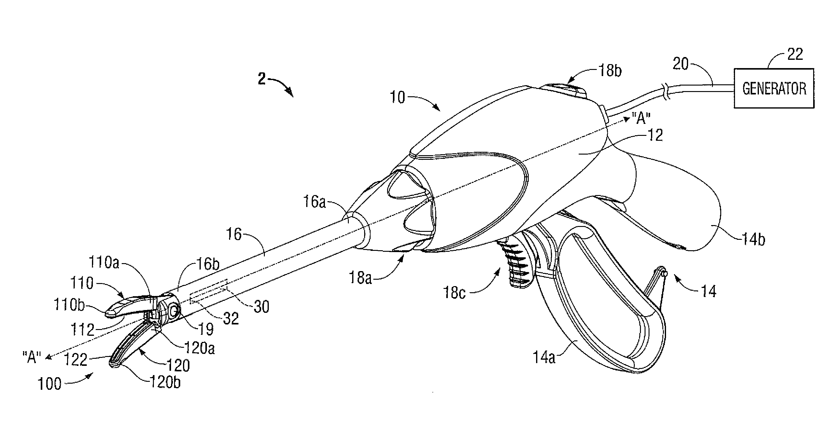
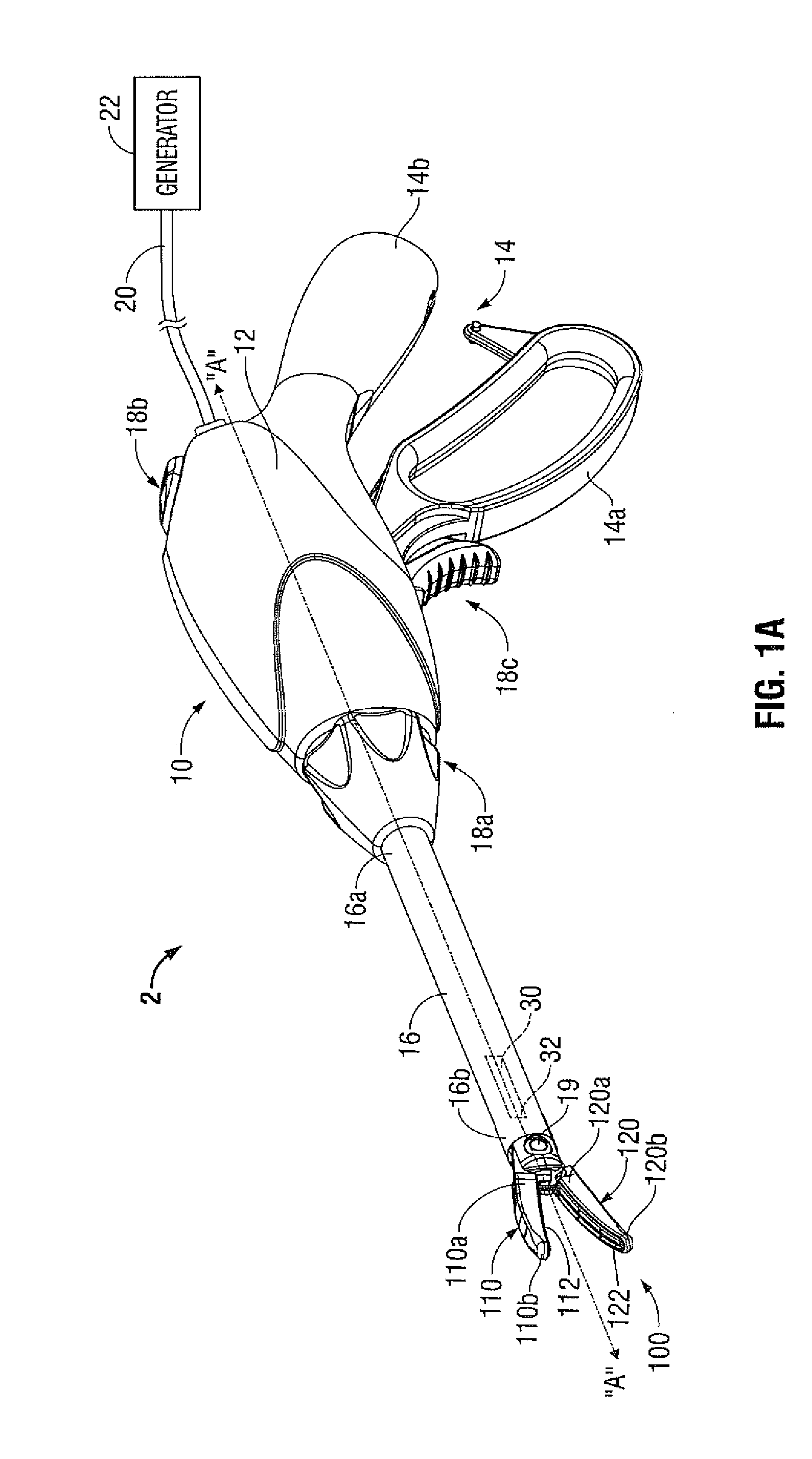
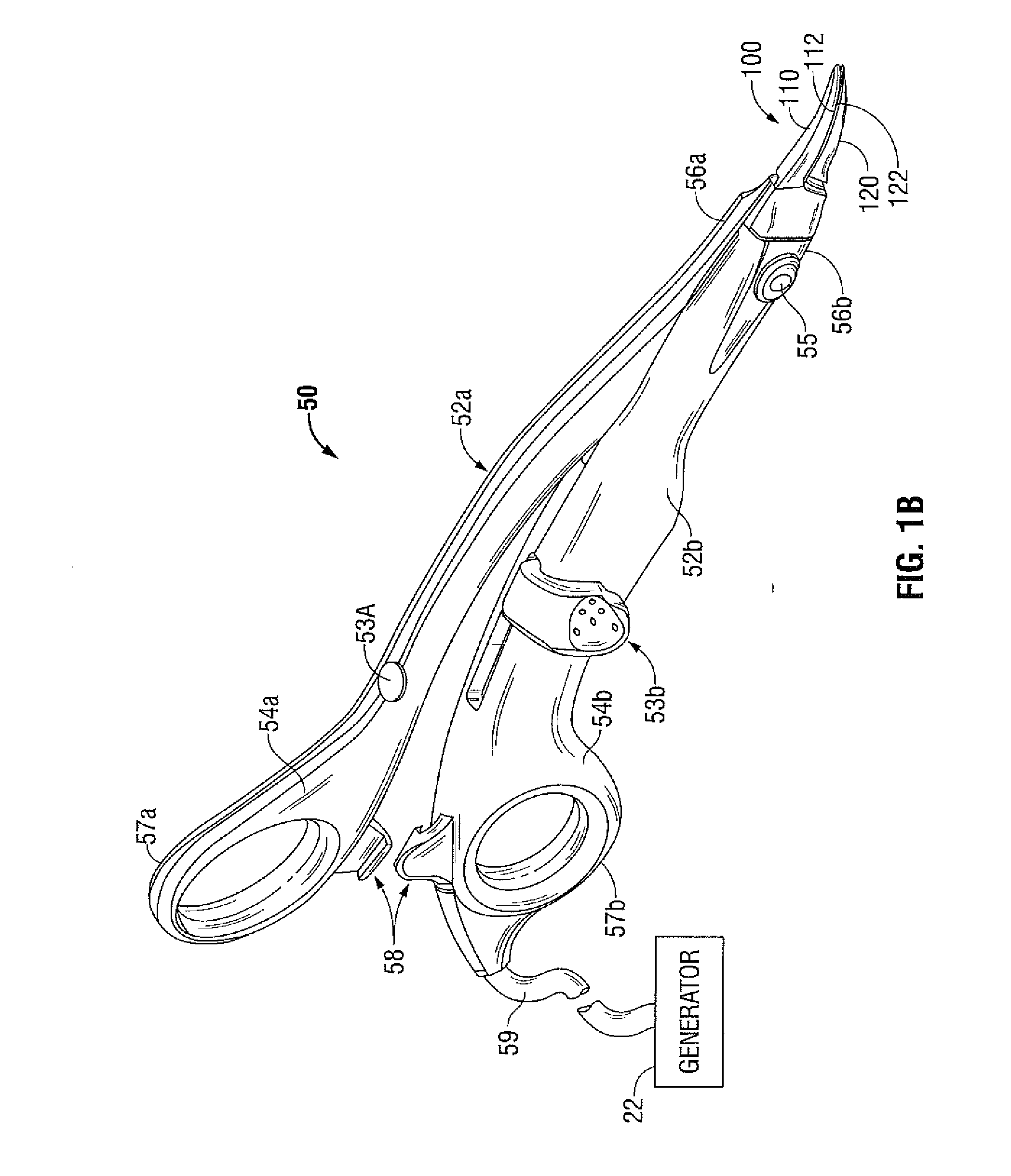
Embodiments of the presently-disclosed electrosurgical instrument are described in detail with reference to the drawings wherein like reference numerals identify similar or identical elements. As used herein, the term “distal” refers to that portion which is further from a user while the term “proximal” refers to that portion which is closer to a user. As used herein, the term “monolithic jaw member” refers to a jaw member of an end effector for a bipolar electrosurgical device having a one-piece configuration. More specifically, a major portion of the jaw member, including the electrode surface (e.g., a sealing surface) is machined from a one-piece conductive material, for example, but not limited to stainless steel. When the monolithic jaw member is configured to have a cutting channel, the cutting channel is machined (e.g., bored) into and along the length of the jaw member such that a cutting element may travel therethrough.

The present disclosure relates to modifying sealing cha...


PUM

PropertyMeasurementUnit
Lengthaaaaaaaaaa
Lengthaaaaaaaaaa
Massaaaaaaaaaa

Abstract

The present disclosure relates to an end effector assembly for use with an electrosurgical instrument and methods of manufacturing the same. The end effector assembly includes a pair of opposing first and second jaw members and a jaw insert. Each of the opposing jaw members has a tissue contacting surface and one or more of the jaw members are monolithic. Additionally, at least one of the jaw members is moveable relative to the other from a first, open position to a second, closed position for grasping tissue. The monolithic jaw member also has a cavity defined therein. The jaw insert is selectively positionable within the cavity of the monolithic jaw member. The jaw insert includes a tissue contacting surface and a portion of the jaw insert includes a dielectric material configured to reduce the thermal mass of the monolithic jaw member.

Description

BACKGROUND1. Technical FieldThe present disclosure relates to varying sealing characteristics of a bipolar electrosurgical instrument with a monolithic jaw member. More particularly, the present disclosure relates to varying sealing characteristics by using a dielectric insert within a monolithic jaw member.2. Description of Related ArtOpen or endoscopic electrosurgical forceps utilize both mechanical clamping action and electrical energy to effect hemostasis. The electrode of each opposing jaw member is charged to a different electric potential such that when the jaw members grasp tissue, electrical energy can be selectively transferred through the tissue. Many times monolithic jaw members having a one-piece metallic configuration are utilized during such procedures. The monolithic jaw configuration allows for an efficient and easier manufacturing process, since fewer parts are needed to assemble a single jaw member.Additionally, certain types of open and endoscopic electrosurgical...

Claims


Application Information

Patent Timeline
IPC IPC(8): A61B18/14H01R43/16
CPCA61B17/285A61B17/295A61B18/1445Y10T29/49204A61B2017/2926A61B2017/2929A61B2017/2825
Inventor CHOJIN, EDWARD M.
Owner TYCO HEALTHCARE GRP LP
Why Eureka
Try Eureka