Exhaust gas aftertreatment device

a technology of exhaust gas aftertreatment and exhaust gas, which is applied in the direction of machines/engines, mechanical equipment, separation processes, etc., can solve the problems of insufficient cross-sectional distribution of exhaust gas over the cross-sectional path of the path through which exhaust gas flows, and the inability to optimize exhaust-gas aftertreatment in the downstream catalytic converter. achieve the effect of less pronounced decrease in exhaust-gas temperature and improved mixing of flowing exhaust gas

Pending Publication Date: 2022-04-07
VITESCO TECH GERMANY GMBH
View PDF0 Cites 0 Cited by
  • Summary
  • Abstract
  • Description
  • Claims
  • Application Information

AI Technical Summary

Benefits of technology

[0007]It is therefore the object of the present invention to create a device for exhaust-gas aftertreatment which leads both to improved mixing of the flowing exhaust gas and to a less pronounced decrease in the exhaust-gas temperature, or even to an active increase in the exhaust-gas temperature.

Problems solved by technology

A disadvantage of the arrangement of catalytic converters directly downstream of a turbocharger is in particular that the flow distribution over the cross section of the path through which the exhaust gas flows is not optimal immediately downstream of a turbocharger, which means that the exhaust-gas aftertreatment in a downstream catalytic converter cannot be optimal either.

Method used


Image

  • Exhaust gas aftertreatment device
  • Exhaust gas aftertreatment device

Examples


Embodiment Construction

[0029]The following description of the preferred embodiment(s) is merely exemplary in nature and is in no way intended to limit the invention, its application, or uses.

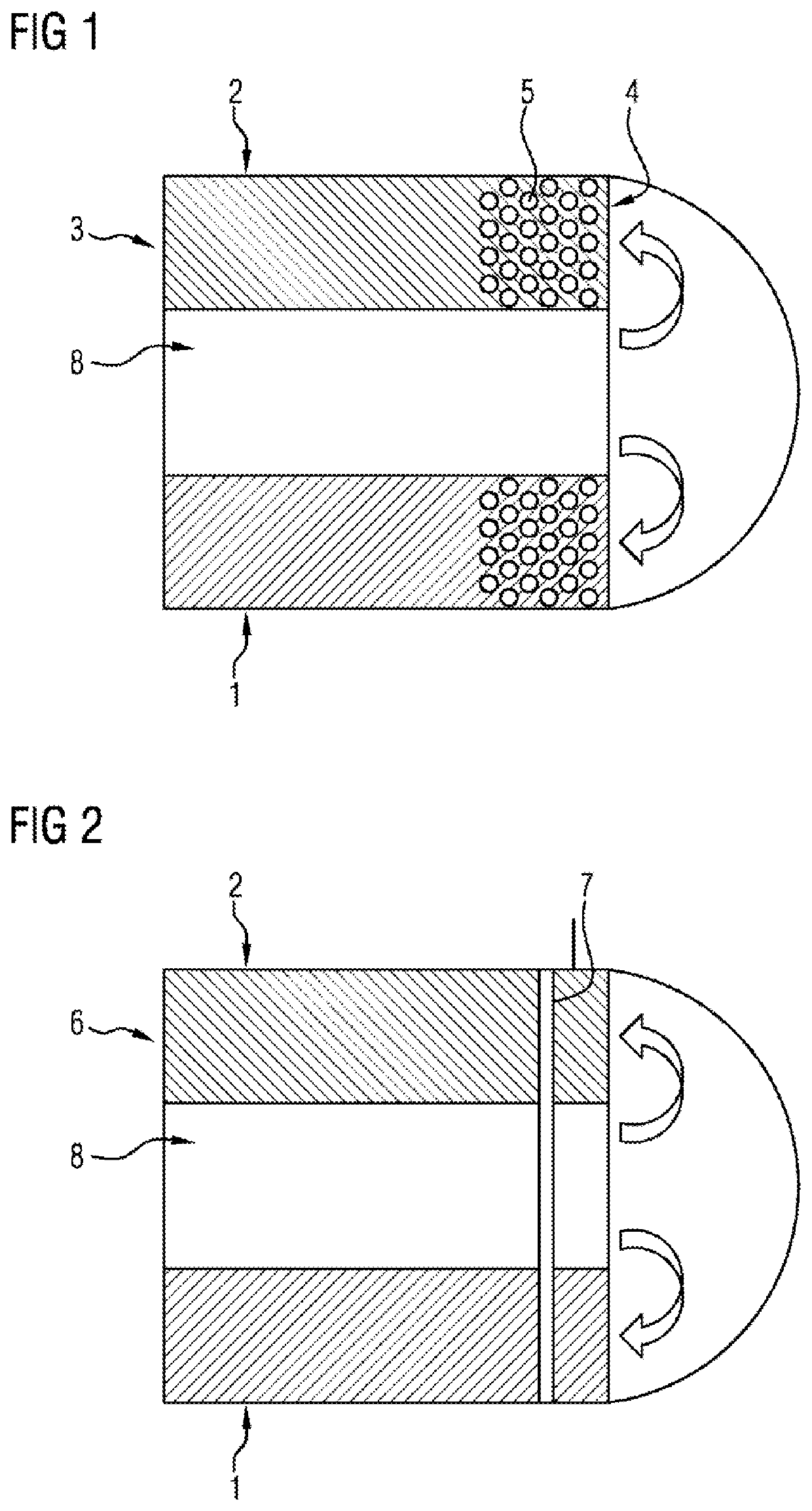
[0030]FIG. 1 shows a sectional view through an annular catalytic converter 1, wherein the substrate body 3 arranged in the annular flow path 2 has a plurality of cutouts 5 at its gas inflow side 4. Because of the cutouts 5, which are for example made in the individual metal foils from which the substrate body 3 is formed, the heat capacity of the substrate body 3 is reduced, which allows faster heating and thus makes it possible for the light-off temperature to be reached more quickly.

[0031]FIG. 2 shows an annular catalytic converter 1 as has already been shown in FIG. 1 In this exemplary embodiment, an electrically heatable heating disk 7 is positioned upstream of the substrate body 6.

[0032]The heating disk 7 may be arranged entirely in the annular flow path 2, or else somewhat upstream thereof in the diverting chamb...


PUM


Abstract

A device for exhaust-gas aftertreatment, such as an annular catalytic converter, having a first, tubular flow path, having a diverting chamber and having a second, annular flow path, wherein the tubular flow path is delimited outwardly in the radial direction by an inner pipe and the second, annular flow path is delimited inwardly in the radial direction by the inner pipe and outwardly in the radial direction by an outer pipe, and the diverting chamber is designed to divert the exhaust-gas flow from the tubular flow path (8) into the annular flow path, wherein the annular catalytic converter has at least one annular substrate body which has a catalytically active coating applied to it and which is arranged in the annular flow path.

Description

CROSS-REFERENCE TO RELATED APPLICATIONS[0001]This application claims priority to PCT Application PCT / EP2020 / 067594, filed Jun. 24, 2020, which claims priority to German Patent Application No. DE 10 2019 209 301.9, filed Jun. 26, 2019. The disclosures of the above applications are incorporated herein by reference.FIELD OF THE INVENTION[0002]The invention relates to a device for exhaust-gas aftertreatment, such as an annular catalytic converter, having a first, tubular flow path, having a diverting chamber and having a second, annular flow path, wherein the tubular flow path is delimited outwardly in the radial direction by an inner pipe and the second, annular flow path is delimited inwardly in the radial direction by the inner pipe and outwardly in the radial direction by an outer pipe, and the diverting chamber is designed to divert the exhaust-gas flow from the tubular flow path into the annular flow path.BACKGROUND OF THE INVENTION[0003]In order to ensure the fastest and most eff...

Claims


Application Information

Patent Timeline
Patent Type & Authority Applications(United States)
IPC IPC(8): B01D53/94
CPCB01D53/94F01N3/2803F01N3/08F01N2470/24F01N2470/22F01N2330/02F01N2330/38F01N2240/16F01N3/281F01N3/2006Y02T10/12F01N3/2026F01N2510/00
Inventor BRÜCK, ROLFHIRTH, PETERSCHEPERS, SVENODENTHAL, DAVID
Owner VITESCO TECH GERMANY GMBH
Why Eureka
Try Eureka