
Arrangement for regulating the temperature of the sample space of a microscope

a technology for regulating the temperature of the sample space and the arrangement of the sample space, which is applied in the direction of microscopes, optics, instruments, etc., can solve the problems of large amount of energy and time required for changing the temperature, and the inability to maintain the desired temperature or temperature constancy at the sample location regulating resources, so as to reduce the thermal mass of the elements without a large expenditure on the arrangement

Active Publication Date: 2008-01-31
CARL ZEISS MICROSCOPY GMBH
View PDF6 Cites 1 Cited by
  • Summary
  • Abstract
  • Description
  • Claims
  • Application Information

AI Technical Summary

Benefits of technology

[0020]Due to the drastic reduction in the temperature difference between the front lens of the objective and the heated objective region, the stresses normally occurring within the objective which can lead to material fatigue, for example, are sharply reduced. Since it is sufficient to supply less heat compared to conventional solutions, there is also less of an adverse effect on the cement substances that are used or on the optical characteristics of the objective itself.
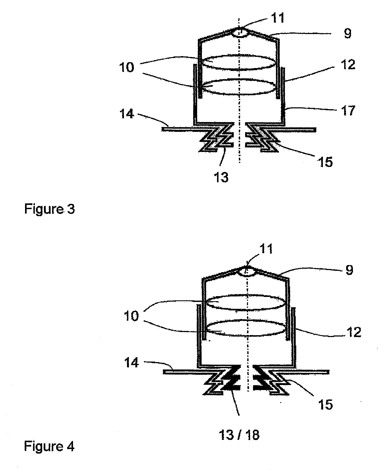
[0022]It is useful when the insulating ring is a component part of the wall of the cylindrical optics carrier and is located as close as possible to the front lens. In this way, as little heat or cold as possible is carried off through the objective.
[0028]Also conceivable is an advantageous further development in which the structural component part blocking the heating flow or cooling flow is the entire optics carrier and / or the entire optics carrier mount. This has the advantage that no additional contours or media are required for connecting the structural component part to parts of the optics carrier or optics carrier mount.

Problems solved by technology

All of the known solutions have the disadvantage that the amount of heat or cold which flows off in the areas remote of the front lens and even in the objective turret is so large that it is impossible to maintain a desired temperature or temperature constancy at the sample location without a very high expenditure with respect to the arrangement and regulating resources.
Further, the thermal mass of the elements is very large so that a large amount of energy and time is required for changing the temperature.

Method used


Image

  • Arrangement for regulating the temperature of the sample space of a microscope
  • Arrangement for regulating the temperature of the sample space of a microscope
  • Arrangement for regulating the temperature of the sample space of a microscope

Examples


Embodiment Construction

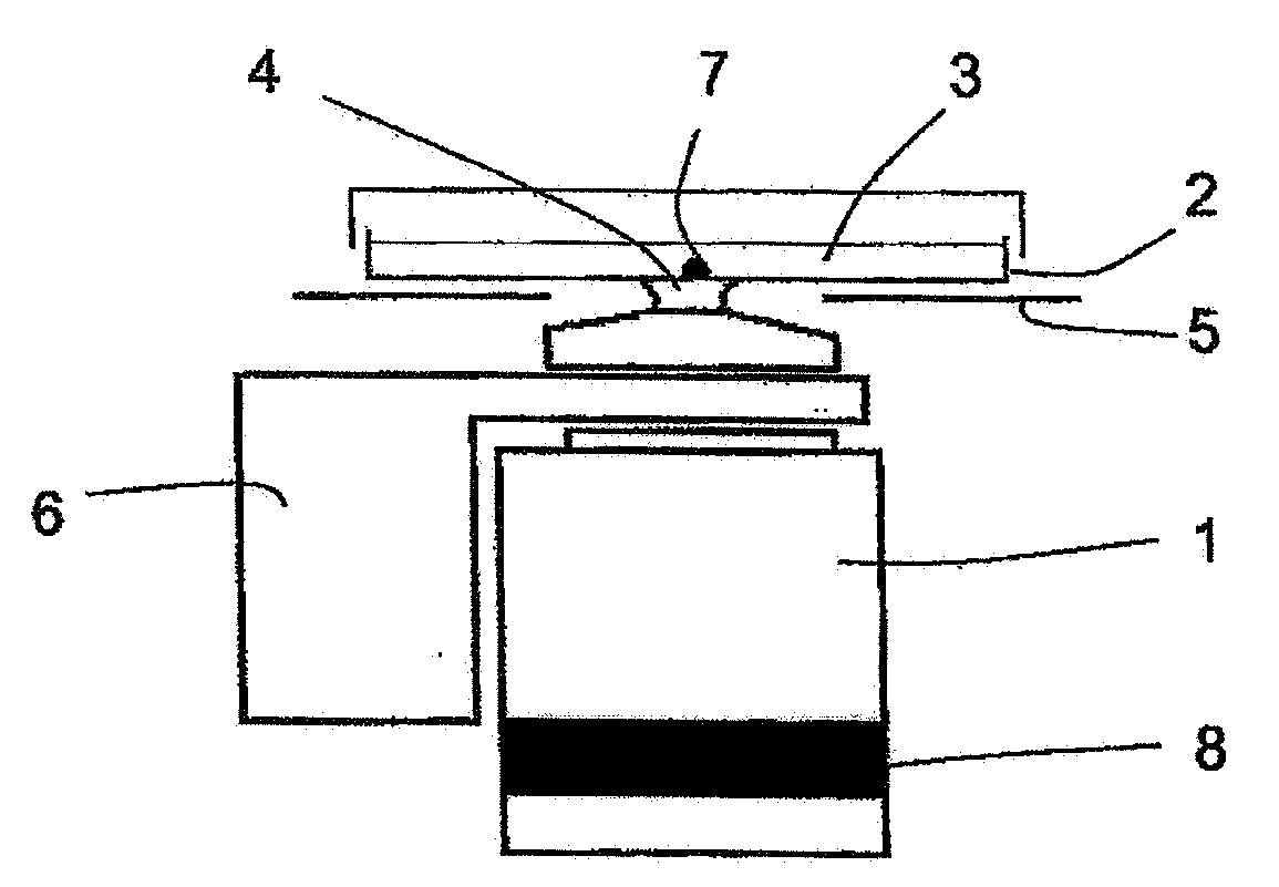
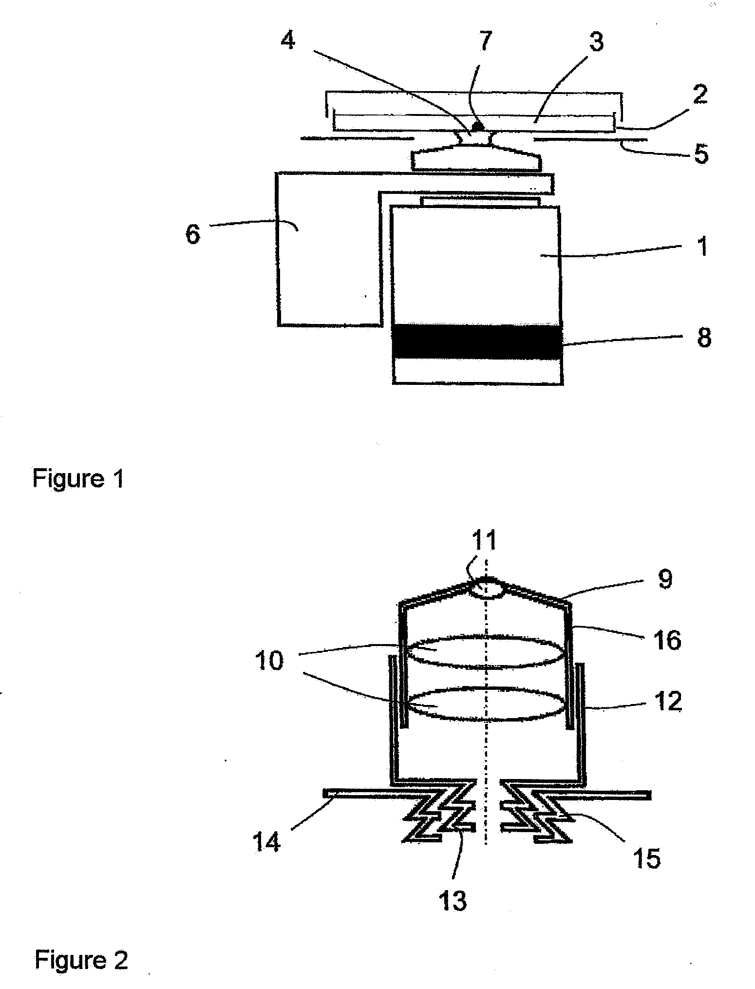
[0040]FIG. 1 shows an embodiment example of the arrangement according to the invention for regulating the temperature of the sample space of a microscope with an inverted microscope body comprising an objective 1 and a sample holder 2 in the form of a Petri dish containing the culture medium 3 in which a sample is to be embedded. The front lens of the objective 2 which is not shown in more detail in FIG. 1 communicates with the sample holder 2 by an immersion liquid 4.

[0041]A heating insert 5 and a heating element 6 which is directly connected to the objective 1 are provided to maintain defined temperature ratios in the sample space. The heating insert 5 and also the amount of heat to be given off by the objective heating element 6 can be controlled by a temperature sensor 7 which is located in the immediate vicinity of the sample to be investigated and by a regulating device, not shown in more detail.

[0042]According to the invention, an insulating ring 8 is located in the objective...


PUM


Abstract

The invention is directed to an arrangement for regulating the temperature of the sample space of a microscope, preferably for observing cells (live cell imaging) with an objective turret carrying objectives, a sample holder serving to receive a sample, a heating or cooling insert with an incubator hood for managing the temperature of the sample holder, and an objective heating element or objective cooling element. According to the invention, at least one structural component part which blocks the heating flow or cooling flow is provided between the objective heating element or objective cooling element and the objective turret.

Description

CROSS-REFERENCE TO RELATED APPLICATIONS[0001]This application claims priority of German Application No. 10 2006 034 534.7, filed Jul. 26, 2006, the complete disclosure of which is hereby incorporated by reference.BACKGROUND OF THE INVENTION[0002]a) Field of the Invention[0003]The invention is directed to an arrangement for regulating the temperature of the sample space of a microscope, preferably for observing living cells (live cell imaging) with an objective turret carrying objectives, a sample holder serving to receive a sample, a heating or cooling insert with an incubator hood for managing the temperature of the sample holder, and an objective heating element or objective cooling element.[0004]b) Description of the Related Art[0005]In microscopic examination of living cells or tissue portions, it is increasingly required to adjust the specific living conditions of the specimen. Apart from taking into account the relative air humidity and the CO2 content, this also includes regu...

Claims


Application Information

Patent Timeline
Patent Type & Authority Applications(United States)
IPC IPC(8): G02B21/26
CPCB01L7/00G02B21/30G02B21/28
Inventor WEHNER, EUGENSCHAFFER, JOERGKLEINSCHMIDT, WERNER
Owner CARL ZEISS MICROSCOPY GMBH
Learn More