Device for detecting transmission losses by means of measurements

a technology of transmission loss and measurement, applied in the direction of testing fibre optic/optical waveguide devices, diagnostics, applications, etc., can solve the problems of high transmission loss of light guide means, failure of overall illumination, and individual fibers of light guide means

Inactive Publication Date: 2005-03-01
FERTON HLDG
View PDF5 Cites 3 Cited by
  • Summary
  • Abstract
  • Description
  • Claims
  • Application Information

AI Technical Summary

Benefits of technology

It is therefore an object of the invention to provide a device for detecting transmission losses of optical light guide means of an endoscope by measurements, said device allowing rapid checking of different light guide means independent of the light source of the endoscopic means.
The arrangement of the light sensor in a diffusely reflecting chamber offers the advantage that the light emerging from the means to be checked can be detected to a large extent independent of its direction and its input cross-section. It is therefore possible to check different light guide means of different manufacturers for their transmission losses. Even the light guide means of endoscopes can be checked without large expenditure and with a high degree of reproducibility of the measured values. The entry of extraneous light at the opening of the chamber is reliably prevented, e.g. with the aid of one or a plurality of flexible seals. The device according to the invention is universally usable, independent of the endoscopic means, and is suitable for quickly examining light guide means prior to an operation. In particular, it is no longer necessary to return an endoscope to the manufacturer for the purpose of examining its transmission losses.
Preferably, it is provided that a separate light source, which is independent of the means to be checked, couples a predetermined light intensity into the optical inlet portion of the light guide means to be checked. The employment of a separate light source offers the advantage that a defined predetermined light intensity can be used for checking purposes without a recalibration of reference values having to be performed for each check. Endoscopic means normally use halogen lamps or gas-discharge lamps. These light sources possess a high radiation power and are mostly controlled such that the adjustment of a reproducible and constant light intensity is difficult. Further, these light sources are subject to an ageing process such that fixed control values also need to be recalibrated. In contrast to this, a constant light intensity can be assumed when an independent checking light source is used which must not be permanently calibrated.
Particulary advantageous is the use of a light-emitting diode as a light source. Since the measurement of the transmission losses does not require high light intensities, it is possible to employ a light-emitting diode. Said diode is inexpensive and can be adjusted by constant-current control to an adequate and highly reproducible light intensity. Calbration is thus not necessary since a fixed and stored reference value can be used for the light source which is solely employed for checking purposes.
According to preferred aspect of the invention the light source is arranged in a connector adapted to standardized connections of the optical inlet portion of the means to be checked. The connector adapted to the standardized connections allows the light source to be quickly connected to the inlet side of the light-conducting means and reliable seating on the means to be checked.
In front of the light sensor a diffusion disk may be arranged which prevents light emerging directly from the light outlet portion of the light guide means to be checked from impinging directly onto the light sensor. The spherical chamber thus ensures insensitivity of the measurement with regard to the direction of the light emerging at the optical outlet portion of the light guide means to be checked and with regard to the exact position of the optical outlet portion inside the chamber.

Problems solved by technology

An examination of endoscopes and associated light guide cables has frequently shown that the light guide means suffer high transmission losses.
Due to mechanical stress, such as bending and winding-up of the light guide cable, tensile stresses when a light guide cable is strongly pulled, bending of the endoscope shaft, and thermal stress during hot-steam sterilization, individual fibers of the light guide means may break.
These deficiencies do normally not lead to an immediate failure of the overall illumination means but to a progressive deterioration of the transmission.
Owing to the gradual transition to higher transmission losses the deterioration of the illumination intensity is frequently detected too late.
If the surgeon notes during an operation that the endoscope used cannot adequately illuminate the operating area, he has to stop the operation in most cases since there is no further sterilized endoscope available to him.
This measuring method is very exact but too complex for quickly checking light guide means in operating theaters.
It is of disadvantage that two light sensors are required which may have different sensitivities and thus have to be calibrated.
It is disadvantageous that the checking means is integrated into an existing endoscopic equipment and cannot be generally used for checking light guide means of an endoscope.

Method used


Image

  • Device for detecting transmission losses by means of measurements
  • Device for detecting transmission losses by means of measurements

Examples


Embodiment Construction

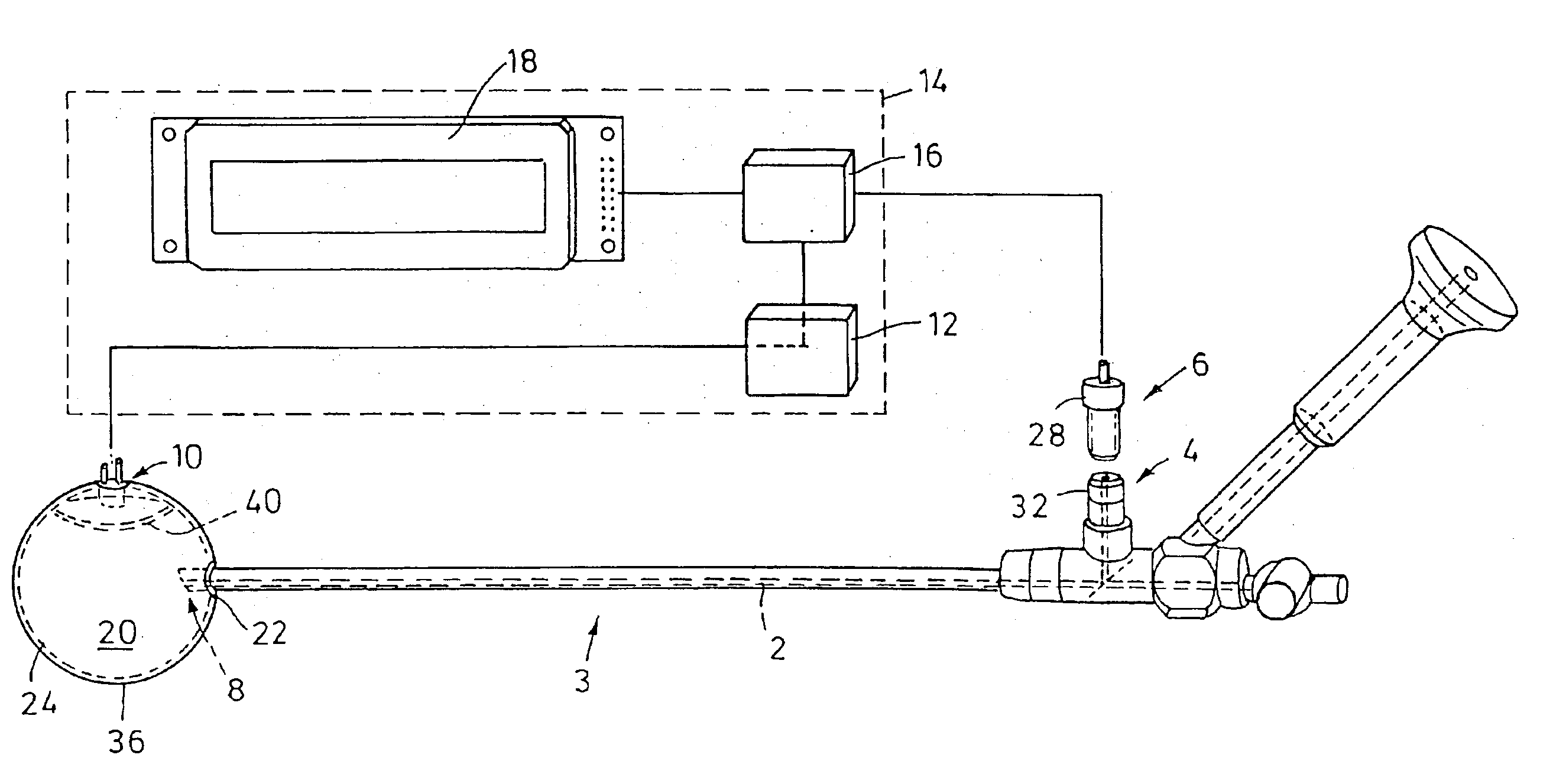
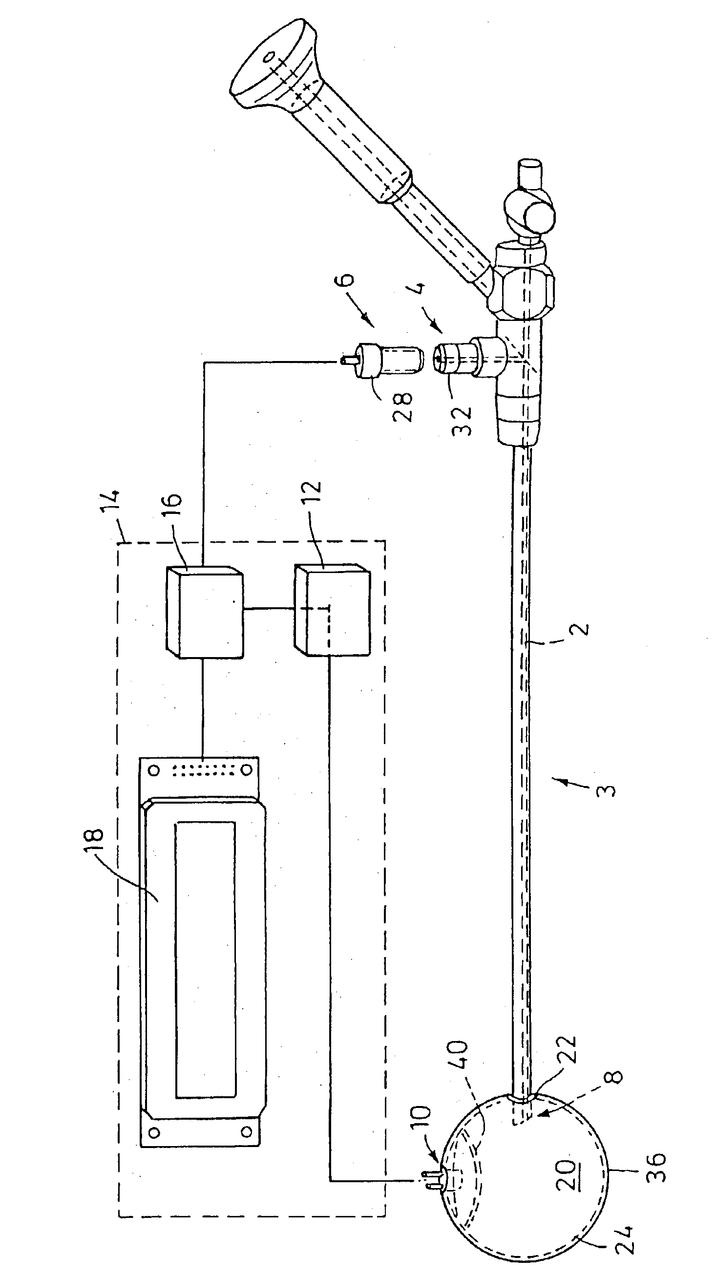
The device for detecting transmission losses of optical light guide means 2 of an endoscope 3 by means of measurements shown in the only FIGURE comprises an evaluation means 14, a light source 6 which is independent of the means 2 to be checked, and a light sensor 10 arranged in a hollow sphere 36.

The evaluation means 14 is provided with a display means 18 for displaying the measurement result, as well as an electronic circuit 16 which comprises on the one hand a constant-current supply unit for a light source 6 consisting of a photodiode, and on the other hand a storage means for reference values for the light source used and for the light guide means to be checked. Further, the electronic circuit 16 comprises an input for the output signal of the at least one light sensor 10, which signal is fed via an amplifier 12 to the electronic circuit 16. The electronic circuit 16 proportions the amplified measuring signal of the light sensor 10 to a predetermined reference value and display...


PUM

PropertyMeasurementUnit
angleaaaaaaaaaa
angleaaaaaaaaaa
light intensityaaaaaaaaaa

Abstract

In a device for detecting transmission losses of optical light guide means (2) of an endoscope (3) by means of measurements, said optical light guide means (2) having an optical inlet portion (4) through which light from a light source (6) is transmitted to an optical outlet portion (8) of the means to be checked, said device comprising at least one light sensor (10) measuring the light intensity emerging from the optical outlet portion (8) of the means (2) to be checked, and an evaluation means (14) for the signal of the at least one light sensor (10), said evaluation means (14) having a display means (18) for displaying the measurement result, it is provided that the at least one light sensor (10) is arranged in a chamber (20), that the optical outlet portion (8) of the light guide means (2) to be checked is adapted to be introduced through an opening (22) of the chamber (20) into the chamber (20), and that the inner surface (24) defining the chamber (20) diffusely reflects the light emerging from the optical outlet portion (8).

Description

BACKGROUND OF THE INVENTIONThe invention relates to a device for detecting transmission losses of optical light guide means of an endoscope by means of measurements.An examination of endoscopes and associated light guide cables has frequently shown that the light guide means suffer high transmission losses. Due to mechanical stress, such as bending and winding-up of the light guide cable, tensile stresses when a light guide cable is strongly pulled, bending of the endoscope shaft, and thermal stress during hot-steam sterilization, individual fibers of the light guide means may break. Frequently, there are deposits on the optical inlet and outlet surfaces of the optical inlet and outlet portions. These deficiencies do normally not lead to an immediate failure of the overall illumination means but to a progressive deterioration of the transmission. Owing to the gradual transition to higher transmission losses the deterioration of the illumination intensity is frequently detected too l...

Claims


Application Information

Patent Timeline
Patent Type & Authority Patents(United States)
IPC IPC(8): G01M11/00
CPCG01M11/33A61B1/00057A61B1/07G02B23/2469A61B1/0655
Inventor HIRT, JOACHIMGLENZER, THOMASKAMP, ARMIN
Owner FERTON HLDG
Why Eureka
Try Eureka