
Frame structure and infrared detector

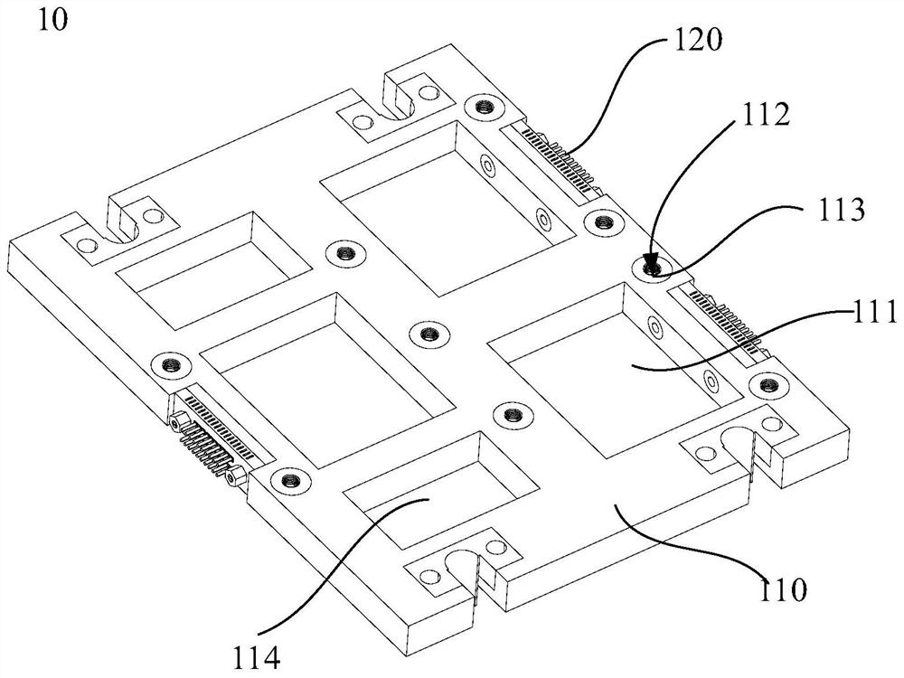
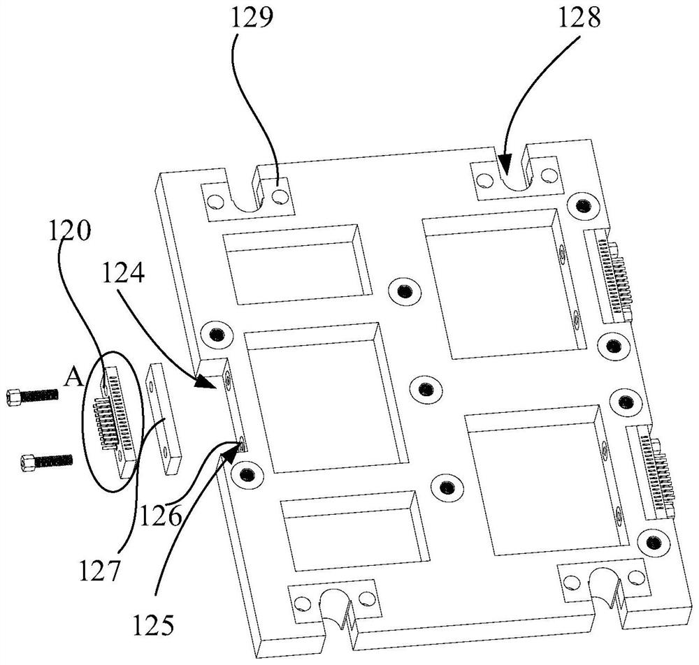
An infrared detector and frame structure technology, which is applied to electrical radiation detectors, instruments, measuring devices, etc., can solve the problems of large energy loss and high requirements on the working power of refrigerators, so as to reduce thermal mass, avoid loss, and reduce thermal mass. Effect

Pending Publication Date: 2022-03-25
北京华鸿锐光科技有限公司
View PDF0 Cites 0 Cited by
  • Summary
  • Abstract
  • Description
  • Claims
  • Application Information

AI Technical Summary

Problems solved by technology

Most of the existing technical solutions use the all-metal substrate as a support to splice multiple infrared detector chips, and the cooling method when the infrared detector is working adopts an integrated cooling method. When the infrared detector is cooled, it needs to cool the all-metal substrate, which requires a high working power of the refrigerator and a large energy loss.

Method used


Image

  • Frame structure and infrared detector
  • Frame structure and infrared detector
  • Frame structure and infrared detector

Examples


Embodiment Construction

[0023] In order to make the purposes, technical solutions and advantages of the embodiments of the present application clearer, the technical solutions in the embodiments of the present application will be clearly and completely described below in conjunction with the drawings in the embodiments of the present application. Obviously, the described embodiments It is a part of the embodiments of this application, not all of them. The components of the embodiments of the application generally described and illustrated in the figures herein may be arranged and designed in a variety of different configurations.

[0024] Accordingly, the following detailed description of the embodiments of the application provided in the accompanying drawings is not intended to limit the scope of the claimed application, but merely represents selected embodiments of the application. Based on the embodiments in this application, all other embodiments obtained by persons of ordinary skill in the art w...


PUM


Abstract

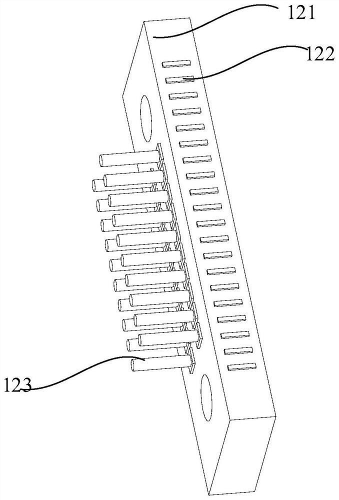
The invention discloses a frame structure and an infrared detector, and relates to the technical field of electronic components, the frame structure comprises a substrate, the substrate is provided with a plurality of through holes, the substrate is provided with a plurality of nut holes around the peripheries of the through holes, and an infrared detector chip is erected on the through holes. The nut hole is used for a nut to pass through so as to fix the infrared detector chip. According to the frame structure and the infrared detector, the thermal mass can be effectively reduced, and the power consumption of a refrigerator is reduced.

Description

technical field [0001] The present application relates to the field of electronic components, in particular, to a frame structure and an infrared detector. Background technique [0002] As a sensor capable of detecting infrared bands, infrared detector chips are widely used in aerospace and other fields. Two important performance indicators of infrared detectors are field of view and resolution. The expansion of the field of view can increase the observation range of the instrument, and the improvement of the resolution can improve the imaging quality of the instrument. In an infrared imaging system, the focal length of the optical system and the size of the detector determine the field of view of the system, and the focal length and pixel size of the optical system determine the resolution efficiency of the system. In the case of a certain detector target surface, in order to improve the overall indicators such as the working distance and resolution of the imaging system,...

Claims


Application Information

Patent Timeline
IPC IPC(8): H01L31/0203H01L31/024H01L31/09G01J5/04G01J5/20G01J5/48
CPCH01L31/0203H01L31/024H01L31/09G01J5/20G01J5/041G01J2005/0077
Inventor 鲍哲博
Owner 北京华鸿锐光科技有限公司
Learn More