Components and methods for milk frothing

A component and heating unit technology, which is applied in the field of components that make milk foam, can solve the problems of valve components that are susceptible to contamination, bacterial growth, complex structure, etc., and achieve the effects of reduced complexity, high energy efficiency, and good stability

Active Publication Date: 2021-12-03
KONINK DOUWE EGBERTS BV
View PDF15 Cites 0 Cited by
  • Summary
  • Abstract
  • Description
  • Claims
  • Application Information

AI Technical Summary

Problems solved by technology

The known devices therefore have a relatively complex structure in order to subsequently provide hot and cold foamed milk in a short time
Valve assemblies used to switch between two parallel channels are susceptible to contamination and bacterial growth

Method used


Image

  • Components and methods for milk frothing
  • Components and methods for milk frothing
  • Components and methods for milk frothing

Examples


Embodiment Construction

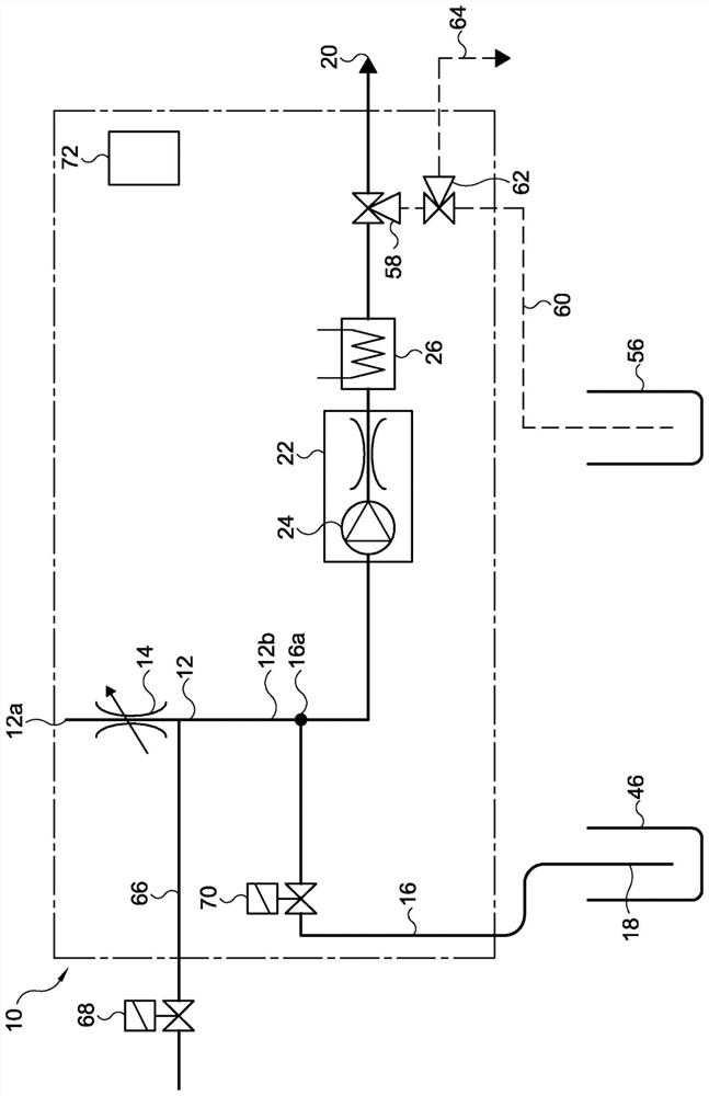
[0047] In most general terms, the assembly 10 for frothing milk comprises an air supply assembly comprising an air source and an air channel 12 having an air inlet 12a and a downstream end 12b. An air source is connected to the air inlet 12a. In one embodiment, the air supply assembly can be configured to control the flow of air supplied to the downstream end. This can be achieved by an air pump connected to the air inlet 12 a and capable of producing a variable flow or by a controllable air valve 14 installable in the air channel 12 . Assembly 10 also includes a fluid channel 16 extending from fluid inlet 18 to fluid outlet 20 . The fluid channel 16 then comprises: an air inlet exit point 16a connecting the downstream end of the air channel 12b, a bubbling unit 22 comprising a pump 24 and a flow-through heating unit 26 defining a heating unit of a portion of the fluid channel 16 Fluid channel 30 . The flow-through heating unit 26 has an energized state and a non-energized ...


PUM


Abstract

An assembly for frothing milk includes an air supply assembly including an air channel having an air inlet and a downstream end. The assembly also includes a fluid channel extending from the fluid inlet to the fluid outlet. The fluid channel then comprises an air inlet exit point to which the downstream end of the air channel is connected, a bubbling unit comprising a pump and a flow-through heating unit. The flow-through heating unit defines a heating unit fluid channel that is a portion of the fluid channel and that has a small thermal mass and a steep temperature profile.

Description

technical field [0001] The present invention relates to an assembly and method for frothing milk. Background technique [0002] Devices for frothing liquids such as milk are known in the art, eg EP 0.485.350 A1 or WO2008 / 083941 A1 which matured into EP 2.120.656 B1. EP 2.120.656 B1 discloses a device for producing milk foam for milk-based beverages. The device comprises a container containing cold refrigerated milk to be supplied to the device for frothing, and a pump fluidly connectable to the container through a milk duct such that the cold refrigerated milk can be pumped from the container to the pump. The device also includes an air duct having an air inlet and an air outlet, the latter protruding from the milk duct. The device also includes a valve assembly configured to supply a quantity of air to the fluid passage to form a fluid / air mixture. A pump is connected to the flow restriction for frothing the milk / air mixture supplied to the flow restriction by the pump. ...

Claims


Application Information

Patent Timeline
Patent Type & Authority Patents(China)
IPC IPC(8): A47J31/44
CPCA47J31/4489A47J31/4485A23F5/26A23V2002/00A47J31/468A23L2/54A47J31/461A47J31/44A47J31/52F25D25/005
Inventor 艾布拉姆·克里斯蒂安·尼普爱德华·帕特尔
Owner KONINK DOUWE EGBERTS BV
Why Eureka
Try Eureka