Heat exchange device and heat generating element containing device using same

a technology of heat exchange device and heat generating element, which is applied in the direction of air heater, heating type, lighting and heating apparatus, etc., to achieve the effect of reducing maintenance work and facilitating the attachment and removal of the cover

Active Publication Date: 2011-08-11
PANASONIC CORP
View PDF16 Cites 6 Cited by
  • Summary
  • Abstract
  • Description
  • Claims
  • Application Information

AI Technical Summary

Benefits of technology

[0009]With this configuration, it becomes easy to attach and detach the cover, and it is possible to achieve a reduction of a maintenance work from the outer side of the device.

Problems solved by technology

In the case mentioned above, there become issues that an installation operation should be carried out from an outer side of the wall surface, and maintenance can be easily executed from the outer side of the wall surface.

Method used


Image

  • Heat exchange device and heat generating element containing device using same
  • Heat exchange device and heat generating element containing device using same
  • Heat exchange device and heat generating element containing device using same

Examples


embodiment 1

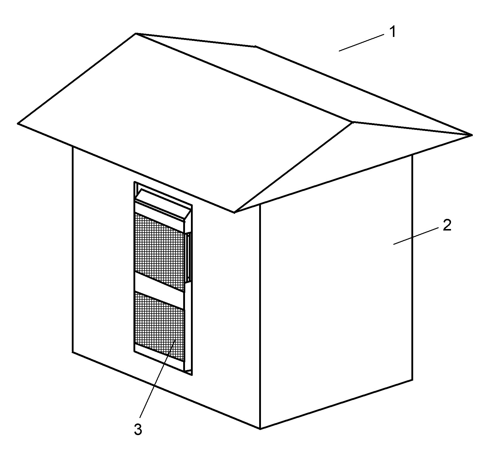
[0029]FIG. 1 is a perspective view showing an embodiment of a heat generating element containing device according to the present invention. Further, FIG. 1 is a perspective view showing a base station provided with a heat exchange device in Embodiment 1 of the present invention. In FIG. 1, base station 1 of a cellular phone is installed in various places. Base station 1 includes box-shaped cabinet 2, and a transmitter receiver which is contained in cabinet 2. One side surface of cabinet 2 is provided with heat exchange device 3 according to the present embodiment in such a manner as to be embedded in a wall surface forming a side surface from an outer side (an ambient air side).

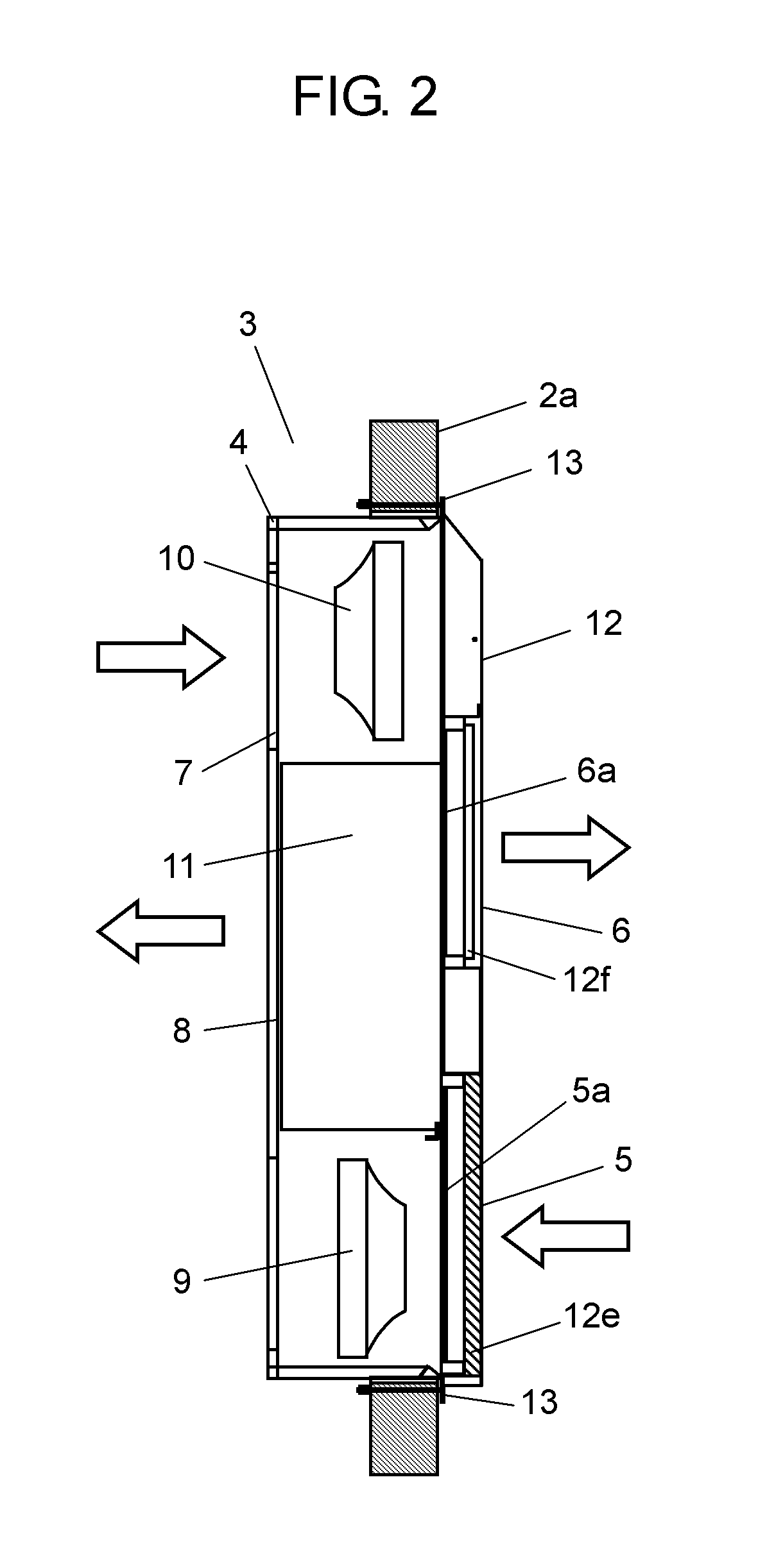
[0030]FIG. 2 is a cross sectional view of a heat exchange device in an embodiment of the present invention. In FIG. 2, heat exchange device 3 is provided with main body case 4 and cover 12 for covering a front surface of main body case 4. Main body case 4 is therein provided with ambient air blower 9 for circ...

embodiment 2

[0042]FIG. 7 is a side cross sectional view of a heat exchange device in Embodiment 2 of the present invention. FIG. 8 is a perspective view of the heat exchange device in the present embodiment in a state where a cover is detached, as seen from an inside air side. Heat exchange device 103 in the present embodiment is fixed to wall surface 105 by main body fixing screw 104 serving as a main body fixing member in such a manner as to be embedded into an opening portion provided in wall surface 105 of cabinet 2 (see FIG. 1). In FIG. 7, a right side is the inside air side, and a left side is an ambient air side.

[0043]Heat exchange device 103 is provided with inside air blower 107 for circulating the inside air to an upper portion in an inner portion of box-shaped main body case 106, and ambient air blower 108 for circulating the ambient air to a lower portion. Further, heat exchange device 103 is provided with heat exchanger 109 for exchanging heat between the inside air circulated by i...


PUM


Abstract

The invention is provided with main body case (4) containing therein an air blower for circulating ambient air and a heat exchanger for exchanging heat between the ambient air circulated by the air blower and inside air, flange (13) provided in main body case (4) and having wall surface joining surface (13b) joined to wall surface (2a) where main body case (4) is arranged, and cover (12) attached to flange (13), having a louver in a side of the inside air, and a plurality of opening holes in a side of the ambient air and covering the ambient air side of main body case (4), thereby making an attachment and a detachment of cover (12) easy, and achieving a reduction of a maintenance work.

Description

TECHNICAL FIELD[0001]The present invention relates to a heat exchange device and a heat generating element containing device using the same.BACKGROUND ART[0002]For example, since a current of several tens amperes or more flows in a base station of a cellular phone, the base station is sometimes expressed as a heat generating element. In other words, it is extremely important for stabilizing the performance thereof to cool. The base station of the cellular phone as mentioned above is provided, for example, with a heat exchange device having a configuration shown in Patent Document 1, for carrying out its cooling.[0003]The base station of the cellular phone includes a cabinet which contains a transmitter receiver serving as the heat generating element, and a heat exchange device which is installed to an opening portion of the cabinet. FIG. 18 is a configuration view of the heat exchange device disclosed in Patent Document 1. In FIG. 18, heat exchange device 201 is provided with main b...

Claims


Application Information

Patent Timeline
Patent Type & Authority Applications(United States)
IPC IPC(8): F28F13/00
CPCF24F12/006F24F13/082F24F13/20Y02B30/563H05K7/206Y02B30/16F24F2221/52Y02B30/56Y02B30/00
Inventor TSUJI, KEISUKEMATSUMOTO, MUTSUHIKOYASUI, NOBUYUKISHIBATA, HIROSHIFUNADA, NAOYUKINAKANO, YUUJISAHASHI, TAKAHIROHAGIMOTO, KEISUKESOGA, HIROTAKAKOGA, KEISUKE
Owner PANASONIC CORP
Why Eureka
Try Eureka