Thermally Controlled Driver/Switching Regulator, and Methods of Controlling and/or Regulating a Driver and/or Switching Regulator

a technology of switching regulators and drivers, applied in the direction of electric variable regulation, process and machine control, instruments, etc., can solve the problems of eventual otp shutdown, increase in boom voltage, and reduction of net voltage across the string, so as to achieve the effect of continuing to function safely

Active Publication Date: 2011-08-11
DONGBU HITEK CO LTD
View PDF4 Cites 42 Cited by
  • Summary
  • Abstract
  • Description
  • Claims
  • Application Information

AI Technical Summary

Benefits of technology

[0011]The present disclosure advantageously provides circuits and methods for regulating and / or controlling integrated circuits, whereby catastrophic shutdown events can be avoided by the use of thermal feedback. Such circuits and methods also advantageously provide an integrated circuit which can continue to function safely even under fault conditions. Another advantage of the technology disclosed in the present application is that a device containing or employing such circuits or methods can operate under temporarily high ambient temperature conditions, and fully recover to normal operation when ambient conditions return to a normal or acceptable level. These and other advantages of the present invention will become readily apparent from the detailed description below.

Problems solved by technology

Each of these faults will usually cause shut down of one or more LED channels, or even the entire IC, to prevent damage to the device.
When a LED channel has an OPEN fault (e.g., OVP=1), the IC will see a large voltage drop across that channel, hence causing the boost voltage to increase.
On the other hand, choosing an OVP threshold voltage that is too high may cause device overheating and eventual OTP shutdown (42) of the device when a LED channel is suddenly opened.
Another LED fault condition is when a particular channel has one or more LEDs shorted in the string (20), causing the net voltage drop across that string to be reduced, resulting in higher power dissipation in that channel.
When a particular channel is disabled, the LCD panel will likely have a dark patch or a streak in the screen.
OVP and OTP fault conditions are usually non-recoverable and require the entire device to be power-cycled before it can operate again.
Due to the a priori nature of the OVP selection process, a lot of guard-banding is typically involved, resulting in a more stringent LED string forward voltage mismatch specification value, which consequently results in higher panel costs.

Method used


Image

  • Thermally Controlled Driver/Switching Regulator, and Methods of Controlling and/or Regulating a Driver and/or Switching Regulator
  • Thermally Controlled Driver/Switching Regulator, and Methods of Controlling and/or Regulating a Driver and/or Switching Regulator
  • Thermally Controlled Driver/Switching Regulator, and Methods of Controlling and/or Regulating a Driver and/or Switching Regulator

Examples


Embodiment Construction

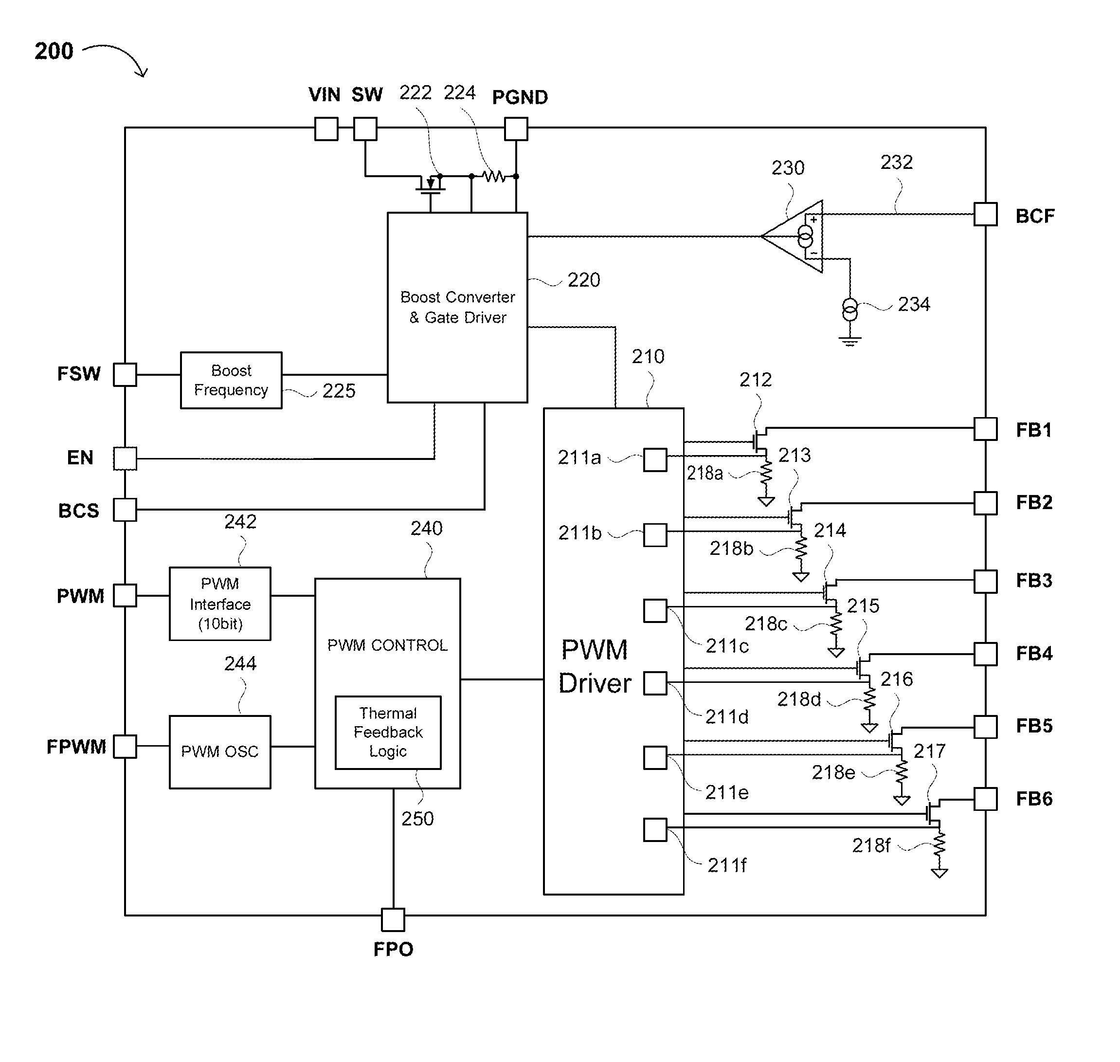
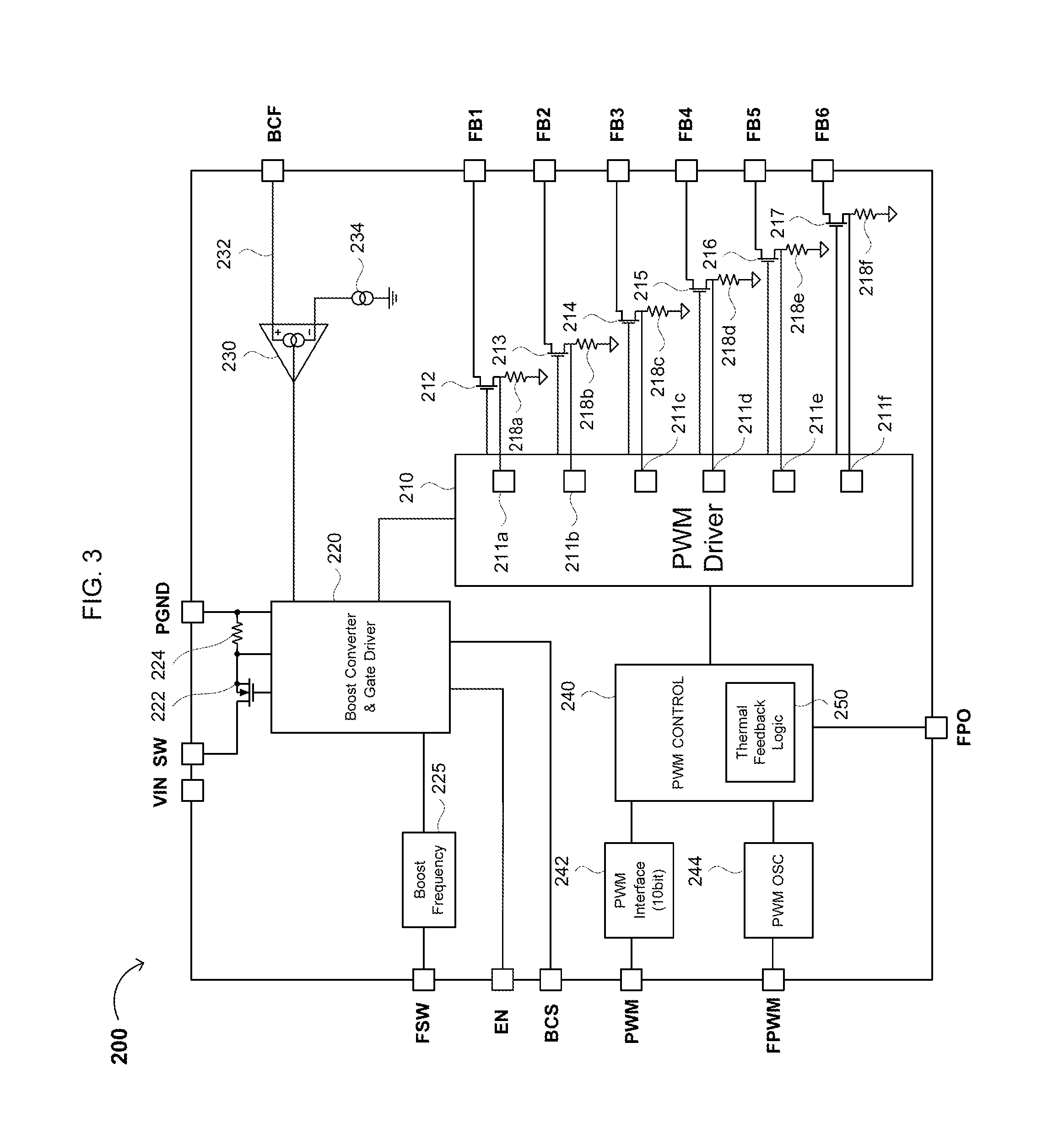
[0018]Reference will now be made in detail to various embodiments of the invention, examples of which are illustrated in the accompanying drawings. While the invention will be described in conjunction with the following embodiments, it will be understood that the descriptions are not intended to limit the invention to these embodiments. On the contrary, the invention is intended to cover alternatives, modifications and equivalents that may be included within the spirit and scope of the invention as defined by the appended claims. Furthermore, in the following detailed description, numerous specific details are set forth in order to provide a thorough understanding of the present invention. However, it will be readily apparent to one skilled in the art that the present invention may be practiced without these specific details. In other instances, well-known methods, procedures, components, and circuits have not been described in detail so as not to unnecessarily obscure aspects of th...


PUM


Abstract

The present invention provides circuits and methods for regulating and / or controlling integrated circuits such as drivers and switching regulators. The circuit generally includes a first switch configured to control or regulate a current, voltage drop or voltage boost; a first regulator or driver configured to transmit first pulses to the first switch, the pulses having a first pulse width; and pulse width modulation circuitry configured to (i) reduce the first pulse width when a first thermal threshold is met and (ii) increase the first pulse width when a second thermal threshold is met, the second thermal threshold being less than the first thermal threshold.

Description

FIELD OF THE INVENTION[0001]The present invention generally relates to the field of analog integrated circuits. More specifically, embodiments of the present invention pertain to drivers, switching regulators, and methods for regulating and / or controlling such integrated circuits.DISCUSSION OF THE BACKGROUND[0002]Four types of fault detection mechanisms usually occur in a typical high-voltage, multi-channel light emitting diode (LED) driver integrated circuit (IC). Referring to FIG. 1, they are LED open 10, LED short 20, over voltage protection (OVP) 30, and over temperature protection (OTP) 40. Each of these faults will usually cause shut down of one or more LED channels, or even the entire IC, to prevent damage to the device.[0003]In a large LCD panel (e.g., at least 10″) using white LEDs (WLEDs) as backlight, each channel typically uses a string of 8-10 WLEDs connected in series. A common boost converter drives the input to the LED strings. Each channel has an independent current...

Claims


Application Information

Patent Timeline
Patent Type & Authority Applications(United States)
IPC IPC(8): G05F1/10
CPCH02M1/32H02M2001/0025H05B33/0887H05B33/0827H05B33/0818H05B45/50H05B45/46H05B47/17H05B45/38H05B45/56H05B45/3725H02M1/0025
Inventor KWOK, KENNETHKRELLNER, JANULBRICH, STEVENPARK, JOON
Owner DONGBU HITEK CO LTD
Why Eureka
Try Eureka