

Key Sharing System
a key processing and key technology, applied in the field of key sharing systems, to achieve the effect of further improving the security of group key agreement techniques
- Summary
- Abstract
- Description
- Claims
- Application Information
AI Technical Summary
Benefits of technology
Problems solved by technology
Method used
Image

Examples
first embodiment
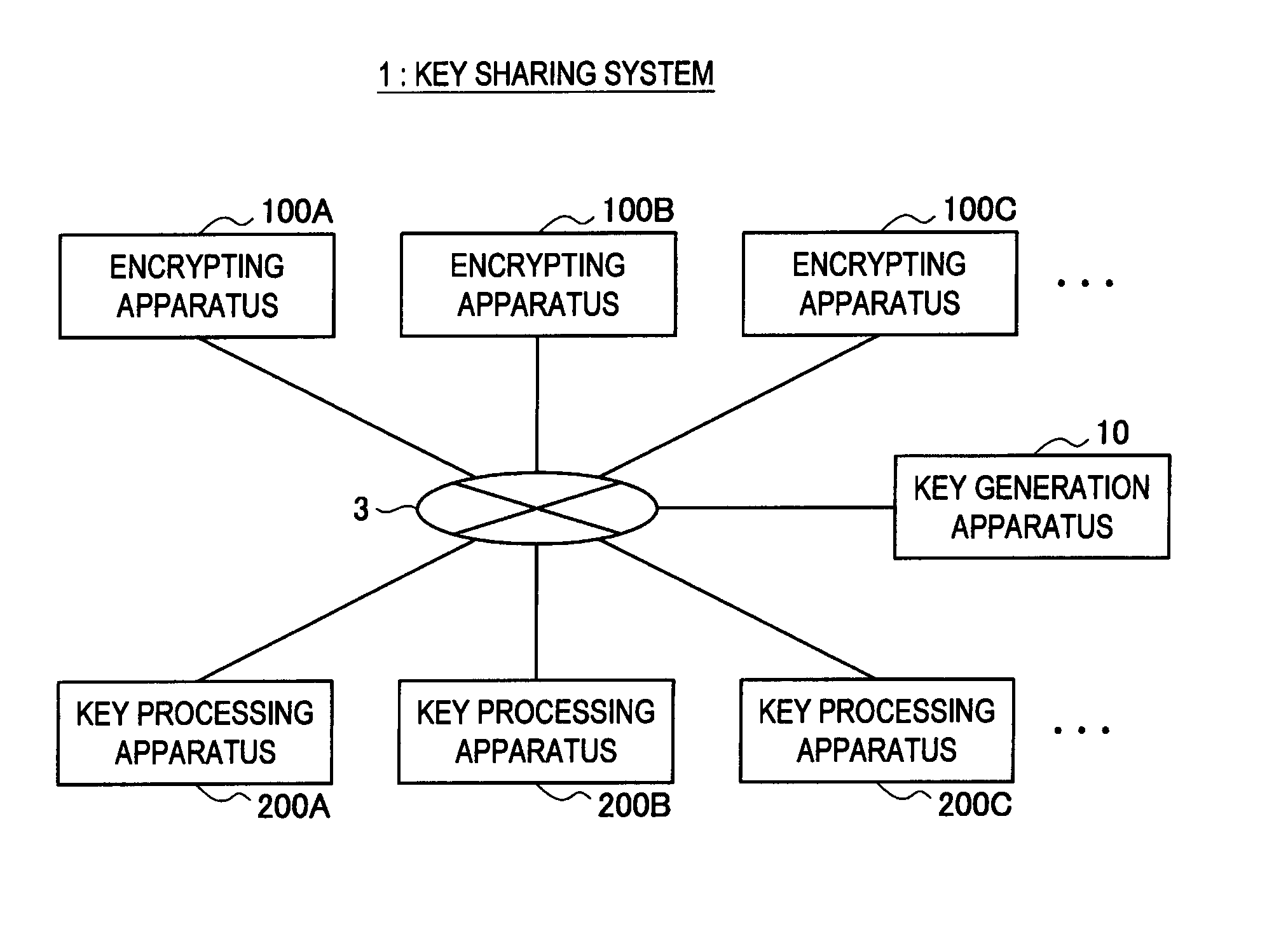
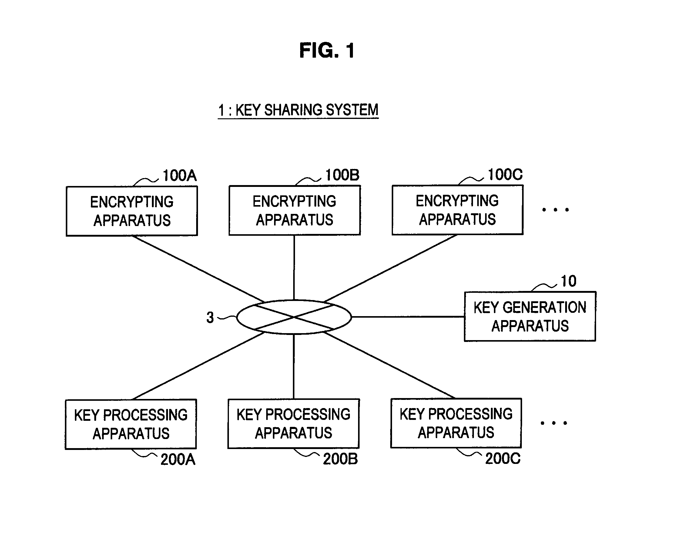
[0200]First, a key sharing system according to the first embodiment of the present invention will be explained in detail with reference to FIG. 1. FIG. 1 is an explanatory diagram illustrating the key sharing system according to the present embodiment.
[0201]For example, as shown in FIG. 1, a key sharing system 1 according to the present embodiment mainly includes a key generation apparatus 10, a plurality of encrypting apparatuses 100A, 100B, 100C . . . , and a plurality of key processing apparatuses 200A, 200B, 200C . . . . These apparatuses are connected with each other via a communication network 3.
[0202]The communication network 3 is a communication circuit network connecting between the key generation apparatus 10, the encrypting apparatuses 100, and the key processing apparatuses 200, so as to enable bidirectional communication or one way communication. This communication network 3 may be constituted by a public circuit network or a dedicated circuit network....
second embodiment
[0313]Subsequently, a key sharing system according to the second embodiment of the present invention will be explained in detail with reference to FIGS. 9 to 11. FIG. 9 is a block diagram illustrating a configuration of an encrypting apparatus 100 according to the present embodiment. FIG. 10 is a block diagram illustrating a configuration of a key processing apparatus 200 according to the present embodiment. FIG. 11 is a flow diagram illustrating session key generation processing according to the present embodiment.
[0314]Like the method described in Non-Patent Literature 3, it is assumed that the key sharing system according to the present embodiment causes a key generation apparatus 10 in a system to generate various kinds of system parameters and individual keys of members. Accordingly, the key generation apparatus 10 publishes system parameters including hash functions, an encryption function E and a decryption function D of public key cryptographic method, a signature generation...
third embodiment
[0374]Subsequently, a key sharing system according to the third embodiment of the present invention will be explained in detail with reference to FIGS. 12 to 16.
[0375]First, the key sharing system according to the present embodiment will be explained in detail with reference to FIG. 12. FIG. 12 is an explanatory diagram illustrating the key sharing system according to the present embodiment.
[0376]For example, as shown in FIG. 12, a key sharing system 1 according to the present embodiment mainly includes a key generation apparatus 10 and a plurality of encrypting apparatuses 100A, 100B, 100C, 100D . . . . These apparatuses are connected with each other via a communication network 3.
[0377]The communication network 3 is a communication circuit network connecting between the key generation apparatus 10 and the encrypting apparatuses 100, so as to enable bidirectional communication or one way communication. The communication network 3 is the same as the communication network 3 according ...
PUM
 Abstract
Description
Claims
Application Information