Shutter device and vacuum processing apparatus

Inactive Publication Date: 2011-08-18
CANON ANELVA CORP
View PDF20 Cites 6 Cited by
  • Summary
  • Abstract
  • Description
  • Claims
  • Application Information

AI Technical Summary

Benefits of technology

[0020]The offset of the shield range can be reduced in the opening/closing operation by using the shutter device according to the invention

Problems solved by technology

That is, a problem arises in that a shield ran

Method used


Image

  • Shutter device and vacuum processing apparatus
  • Shutter device and vacuum processing apparatus
  • Shutter device and vacuum processing apparatus

Examples


first embodiment

[0028

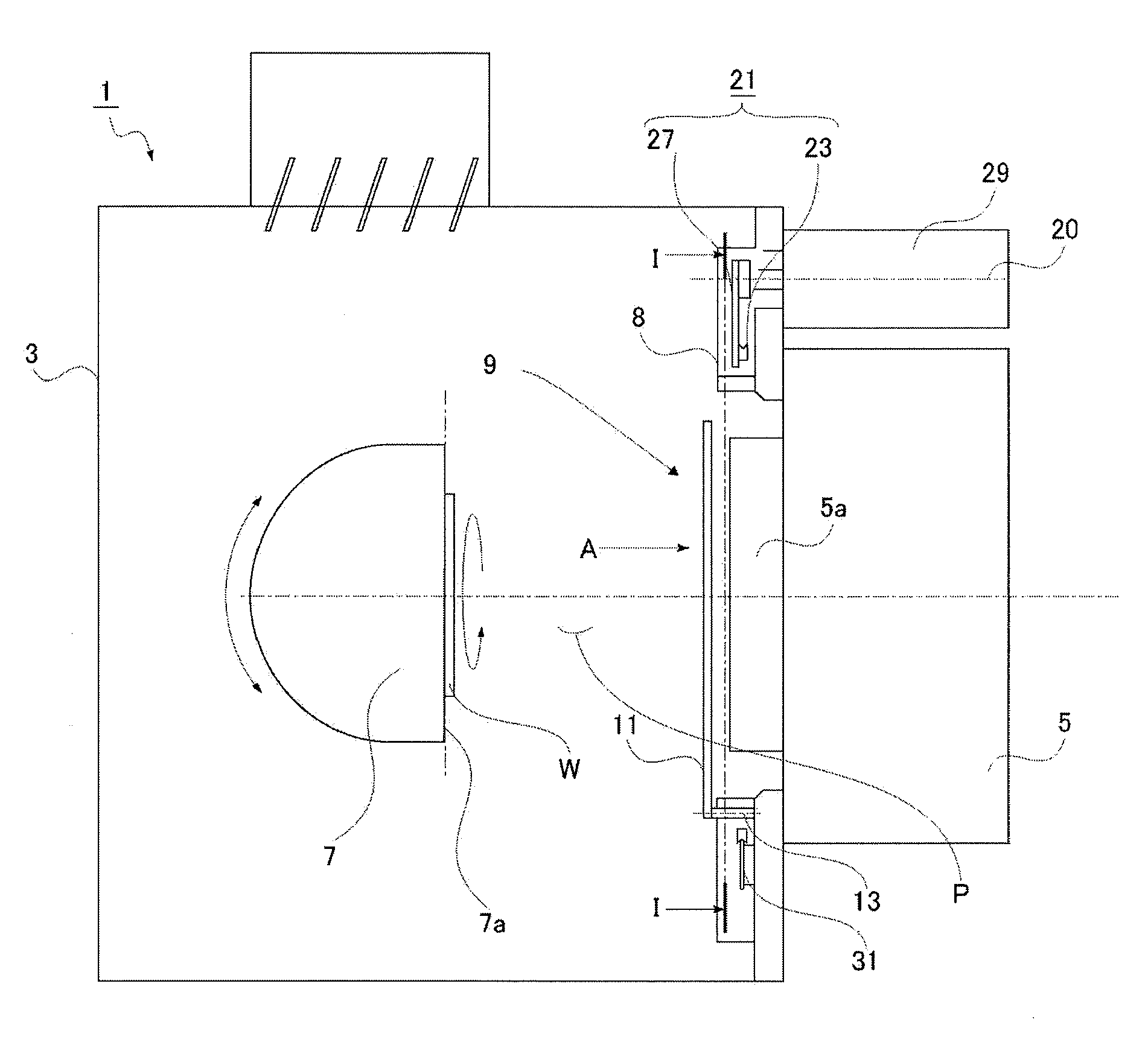
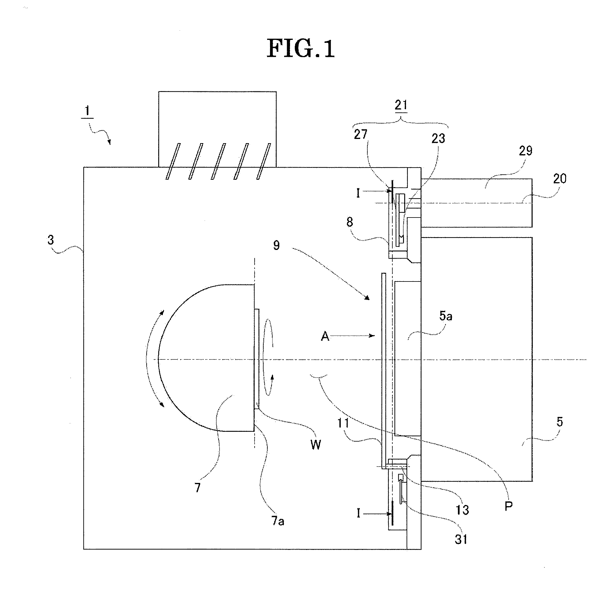
[0029]A first embodiment of the invention will be described below with reference to the drawings. It goes without saying that members, dispositions, and the like described below are an example in which the invention is embodied, do not restrict the invention, and can be variously changed and modified. Note that a term “process-generation-source” in the specification is used to show any of an ion source such as an IBS and the like and an evaporation source such as a sputtering cathode, a crucible, and the like.

[0030]Note that, in the embodiment, although a description is made by exemplifying an ion beam etching apparatus (IBE apparatus) as a vacuum processing apparatus, the invention is not limited to the ion beam etching apparatus. The shutter device according to the invention can be preferably applied also to a vacuum processing apparatus, for example, other etching apparatus and sputtering apparatus, a PVD apparatus, a CVD apparatus, and the like. Even when the shutter device...

second embodiment

[0053

[0054]FIGS. 5A and 5B are front views of a shutter device according to a second embodiment of the invention, and FIG. 5A and 5B show a closed state and an open state of the shutter device, respectively. Note that, in the embodiment described below, members, dispositions, and the like which are the same as those of the first embodiment are denoted by the same reference numerals and a detailed explanation thereof will not be repeated here.

[0055]In the shutter device 39 according to the embodiment, a shutter is divided to eight shutter plates. The eight shutter plates 41 have shutter rotating shafts 43, respectively, as well as are coupled with coupling link members 45. Note that the respective coupling link members 45 are coupled with a rotation link member 23 likewise the shutter device according to the first embodiment. Further, since a support mechanism of the coupling link members 45 supported by bearings 31, a coupling structure of the coupling link members 45 with a drive l...


PUM

PropertyMeasurementUnit
Poweraaaaaaaaaa
Distanceaaaaaaaaaa
Symmetryaaaaaaaaaa

Abstract

A shutter device having two shutter plates, which shield between an IBS and a substrate, is configured such that the two shutter plates are disposed at symmetrical positions across the IBS and can perform an opening/closing operation in synchronization with a rotation of a rotation-link-member which is rotatably disposed surrounding the IBS. With the configuration, the shutter device can reduce an offset of a shield range in the opening/closing operation.

Description

BACKGROUND OF THE INVENTION[0001]1. Field of the Invention[0002]The invention relates to a shutter device and a vacuum processing apparatus, and more particularly to a shutter device including shutter plates which shield between an ion source or an evaporation source and a substrate when respective processes are performed in a vacuum processing apparatus such as a sputtering device, an etching apparatus, and the like and to a vacuum processing apparatus including the shutter device.[0003]2. Description of the Related Art[0004]A physical vapor deposition device and an etching device are ordinarily used as a vacuum processing apparatus. The physical vapor deposition device includes an evaporation source such as a crucible, a cathode, and the like, and further the etching device includes an etching source such as an ion source and the like. It is preferable to make a film forming material and an ion beam generated from the evaporation source and the etching source uniform and stable. F...

Claims


Application Information

Patent Timeline
IPC IPC(8): C23F1/02C23C14/34B05C11/00
CPCH01J37/045H01J2237/3151H01J37/32623H01J37/32495
Inventor TSUJIYAMA, MASASHI
Owner CANON ANELVA CORP
Why Eureka
Try Eureka