Rigid Retractable Patio or Window Awning and Operating Mechanisms Therefor

a retractable, patio or window technology, applied in the field of retractable patio or window awnings, can solve the problems of insufficient durability of retractable patio awnings, prone to sagging of fabric, and less attractive awnings, and achieve the effect of simple and reliable operating mechanisms

Inactive Publication Date: 2011-08-18
SVIRSKY ALEXANDER +1
View PDF18 Cites 32 Cited by
  • Summary
  • Abstract
  • Description
  • Claims
  • Application Information

AI Technical Summary

Benefits of technology

[0011]An object of the present invention is to provide a rigid retractable patio awning that may be fully retracted when shade is not required.
[0012]Another object of the present invention is to provide a rigid retractable patio awning that may be extended and retracted by a sufficient distance to cover an average-sized patio.
[0013]A further object of the present invention is to provide a rigid retractable pat

Problems solved by technology

Such known retractable patio awnings, where the cover is made of fabric, are not sufficiently durable, as they require periodic replacement of the fabric.
Even before the fabric needs replacement, it fades making the awning appearance less attractive.
Fabric also is prone to sagging and resulting accumulation of water when the awning remains in the extended position during rain.
Such awning may not be fully retracted and always creates shade

Method used


Image

  • Rigid Retractable Patio or Window Awning and Operating Mechanisms Therefor
  • Rigid Retractable Patio or Window Awning and Operating Mechanisms Therefor
  • Rigid Retractable Patio or Window Awning and Operating Mechanisms Therefor

Examples


first embodiment

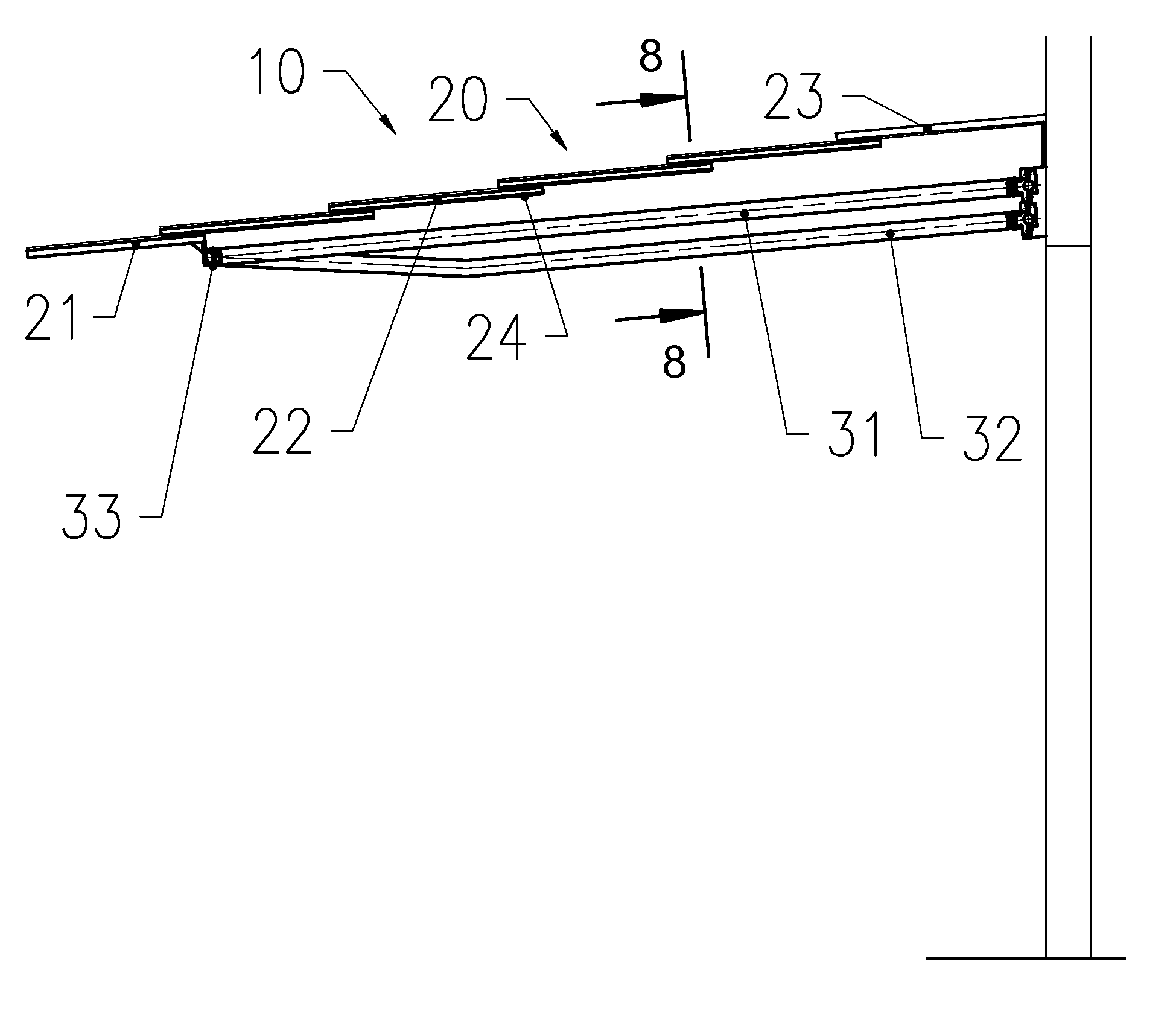
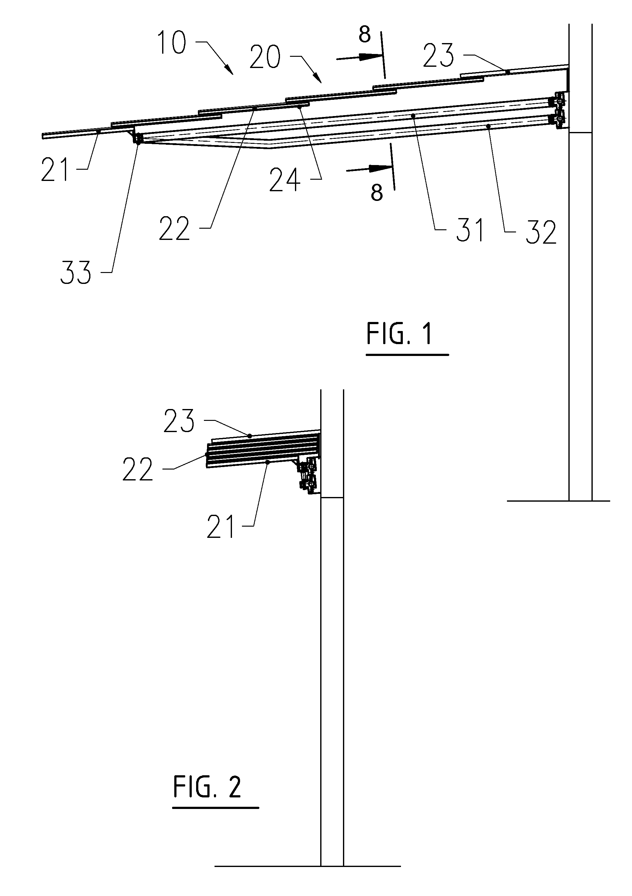
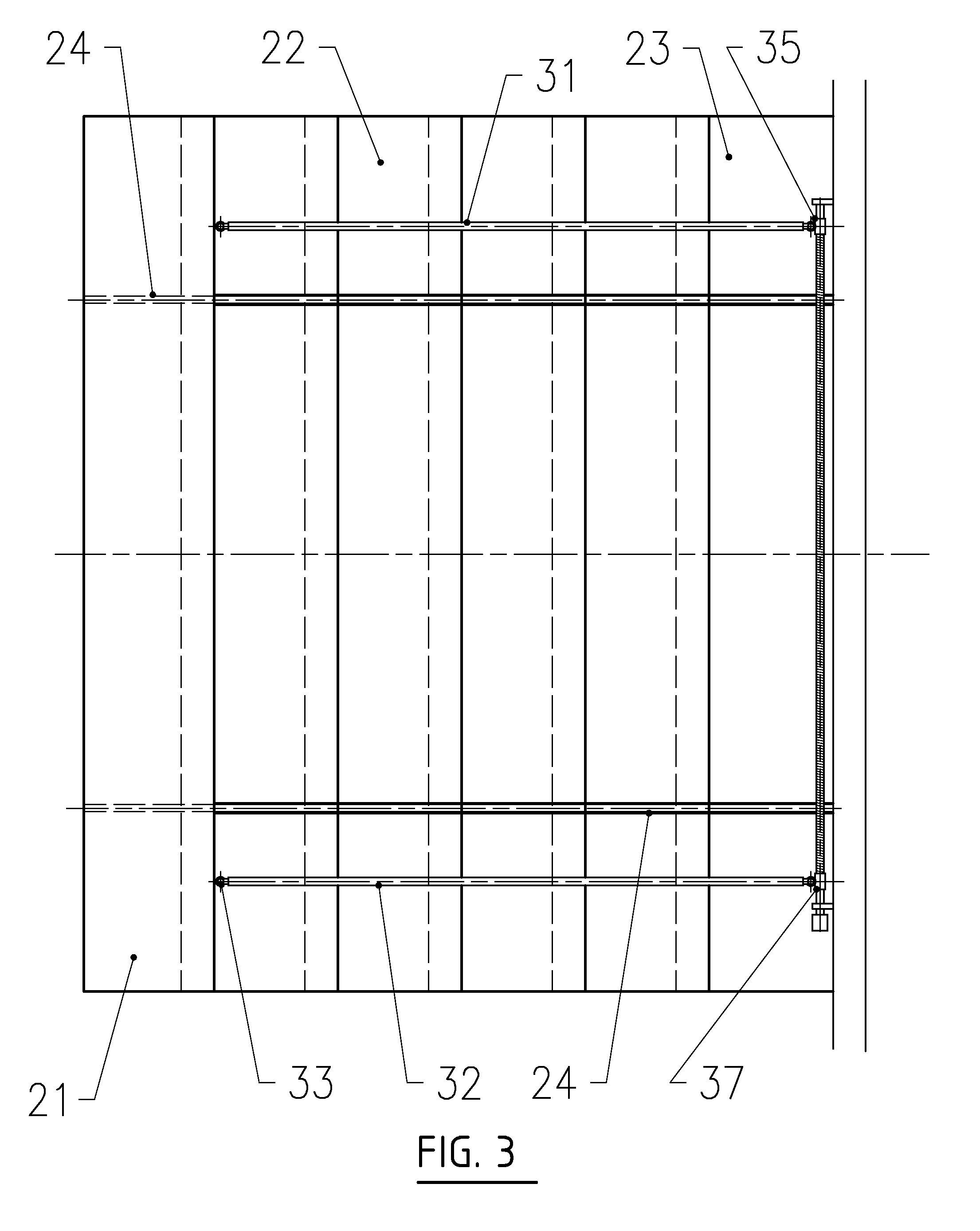
[0032]the present invention shown in FIGS. 1-8 employs an operating mechanism that includes an upper arm 31 and a lower arm 32 connected via swivel joints 33 with the bottom panel 21. The opposite end of the upper arm 31 is movably connected via a swivel joint 34 with a threaded nut 35 engaged with an upper drive screw 36. The opposite end of the lower arm 32 is movably connected via a swivel joint 34 with a threaded nut 37 engaged a lower drive screw 38. Nuts 35 and 37 are slidably connected with a mounting bar 39 via a linear bearing consisting of an upper bearing 41 and a lower bearing 42.

[0033]To extend the awning from its retracted position shown in FIGS. 2 and 4 to its extended position shown in FIGS. 1 and 3, the drive screws 36 and 38 are rotated so that the nuts 35 and 37 travel toward each other, which causes the arms 31 and 32 to push the bottom panel 21 outwardly and the bottom panel 21 to pull along the intermediate panels 22. The nuts 35 and 37 continue traveling in th...

second embodiment

[0034]the present invention is shown in FIGS. 9 and 10 and is suitable for a situation where a shorter awning projection distance is sufficient. Such situation may be present in wide and relatively shallow patios or when the awning is used over windows. In this embodiment the operating mechanism includes a left arm 51 and a right arm 52 connected via swivel joints 33 with the bottom panel 21. A drive screw 61 includes a left section 62 and a right section 63 threaded in opposite directions. The left arm 51 and the right arm 52 are connected via swivel joints 34 with threaded nuts 53 and 54 engaged, respectively, with the left drive screw section 62 and the right drive screw section 63.

[0035]To retract the awning in its second embodiment shown in FIGS. 9 and 10, the drive screw 61 is rotated so that the nuts 53 and 54 travel toward each other along the drive screw 61, which causes arms 51 and 52 to pull the bottom panel 21 and any intermediate panels. To extend the awning, the drive ...

third embodiment

[0036]the present invention shown in FIGS. 11, 12, 13 and 14 employs an operating mechanism that includes a left arm 71 and a right arm 81. The arms 71 and 81 include proximate sections 72 and 82 respectively and distant sections 73 and 83 respectively. Arm sections 72 and 73 are connected via swivel joints 74 with a threaded nut 75. Arm sections 82 and 83 are connected via swivel joints 84 with a threaded nut 85. The proximate sections 72 and 82 are connected via swivel joints 76 with a mounting bar 88. The distant sections 73 and 83 are connected via swivel joints 77 with a bottom panel 21. The nuts 75 and 85 are engaged with a drive screw 95 that includes a left section 96 and a right section 97. The drive screw sections 96 and 97 are threaded in opposite directions.

[0037]To extend the awning, as shown in its retracted position in FIGS. 12 and 14, the drive screw 95 is rotated so that the nuts 75 and 85 travel in opposite directions toward the ends of the drive screw 95. To retra...


PUM


Abstract

A rigid retractable patio or window awning includes a number of rigid panels disposed in a tiered relationship with each other. Each lower panel is slidably connected with its respective upper panel via a set of slides. The top panel remains stationary. An awning operating mechanism includes arms connected via swivel joints with the bottom panel. Each arm also is connected via a threaded nut with a drive screw. The awning is extended by rotating the drive screw, which causes the nuts to travel along the drive screw causing the arms to push the bottom panel outwardly and the bottom panel to pull along any intermediate panels. The awning is retracted by rotating the drive screw in the opposite direction.

Description

CROSS-REFERENCE TO RELATED APPLICATIONS[0001]Not ApplicableSTATEMENT REGARDING FEDERALLY SPONSORED RESEARCH OR DEVELOPMENT[0002]Not ApplicableREFERENCE TO SEQUENCE LISTING, A TABLE, OR A COMPUTER PROGRAM LISTING COMPACT DISC APPENDIX[0003]Not ApplicableBACKGROUND OF THE INVENTION[0004]The present invention relates to awnings and more particularly to retractable patio or window awnings.[0005]Retractable patio, deck and porch awnings have been known for many years and have gained great popularity. They are used to create shade over decks and patios and also may provide protection from light rain. The retractability feature allows the user to retract the awning when shade is not desired or during severe weather conditions.[0006]In addition, retractable patio awnings provide energy savings by shading doors and patios from direct sunlight and thereby reducing gain of solar heat by the associated building. By lowering temperature inside the building during the air conditioning season, pat...

Claims


Application Information

Patent Timeline
IPC IPC(8): E04F10/08
CPCE04F10/10
Inventor SVIRSKY, ALEXANDER R.SVIRSKY, VLADIMIR
Owner SVIRSKY ALEXANDER
Why Eureka
Try Eureka