Method for extracting landfill gas

a landfill gas and gas extraction technology, applied in fluid removal, borehole/well accessories, mining structures, etc., can solve the problems of escaping lfg emissions, wasting capital, and unable to capture and use a significant energy source, and achieve efficient and effective recovery of lfg. , the effect of enhancing the recovery of lfg

Active Publication Date: 2011-08-18
STAMOULIS STEFAN
View PDF14 Cites 24 Cited by
  • Summary
  • Abstract
  • Description
  • Claims
  • Application Information

AI Technical Summary

Problems solved by technology

Additionally, escaping LFG emissions are a lost opportunity to capture and use a significant energy source.
This is currently accomplished by the advancement of new wells into the upper waste bodies, which can be a capital intensive process.
Traditional attempts to enter non-functional or under-producing methane recovery wells for rehabilitation purposes have been unsuccessful for many various reasons.
For example, such wells are often on side slopes or uneven ground which makes access to the wells with traditional equipment (i.e. a drill rig) very difficult and sometimes impossible.
Additionally, the pipes used for such wells in MSWF are made from a material that often bends and deviates after well installation and during waste placement resulting in wells that are no longer vertical.
This makes traditional re-entry attempts very difficult.
Couplers, lag screws, or similar type fasteners used to connect additional pipes or risers generate obstructions inside the wells, making re-entry near impossible at depths necessary for successful well rehabilitation.
These reasons among others severely limit the available methods to successfully rehabilitate a methane gas recovery well.
Since at least 1993, the need to rehabilitate existing LFG recovery wells has been a recognized unsolved problem.

Method used


Image

  • Method for extracting landfill gas
  • Method for extracting landfill gas
  • Method for extracting landfill gas

Examples


Embodiment Construction

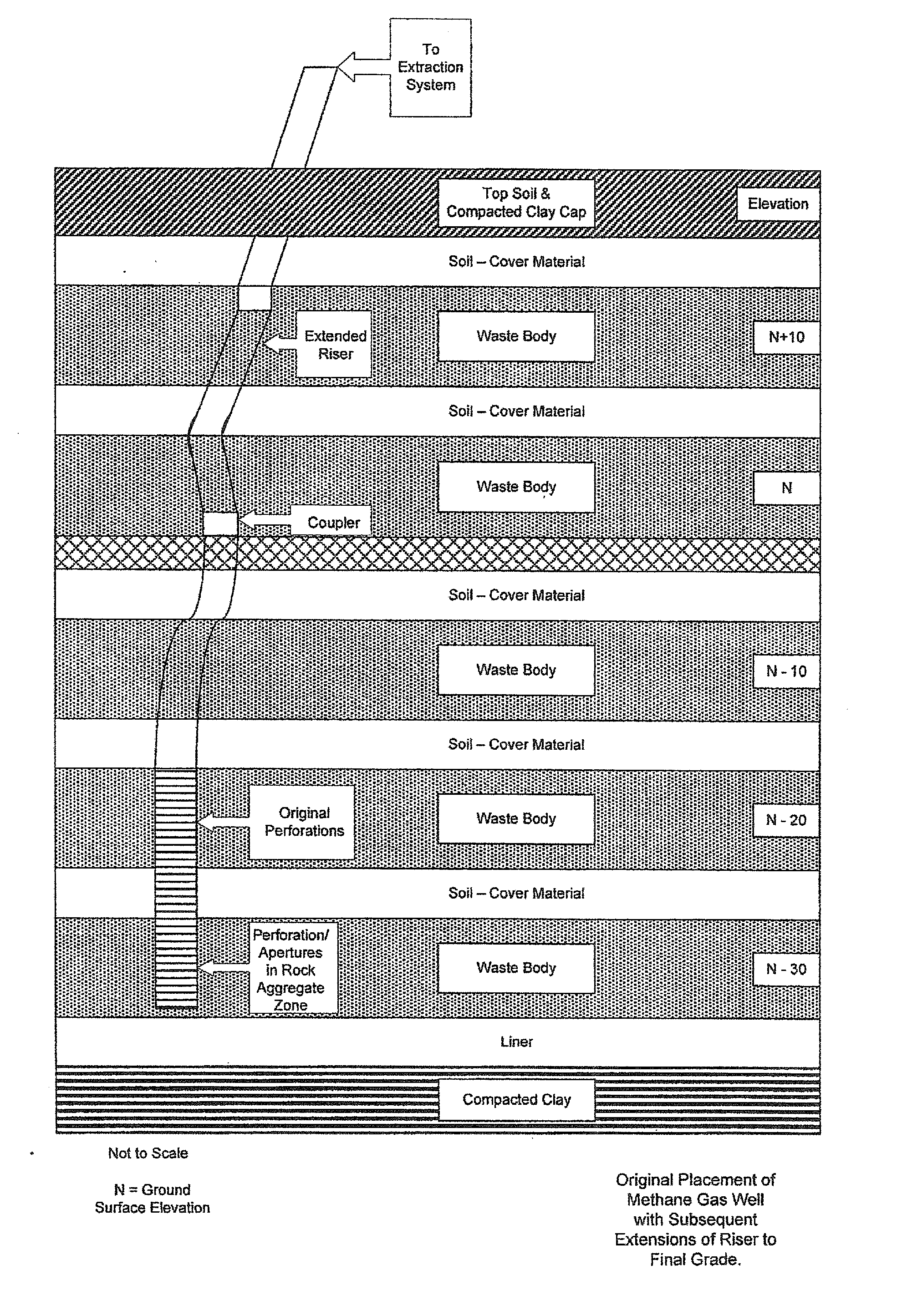
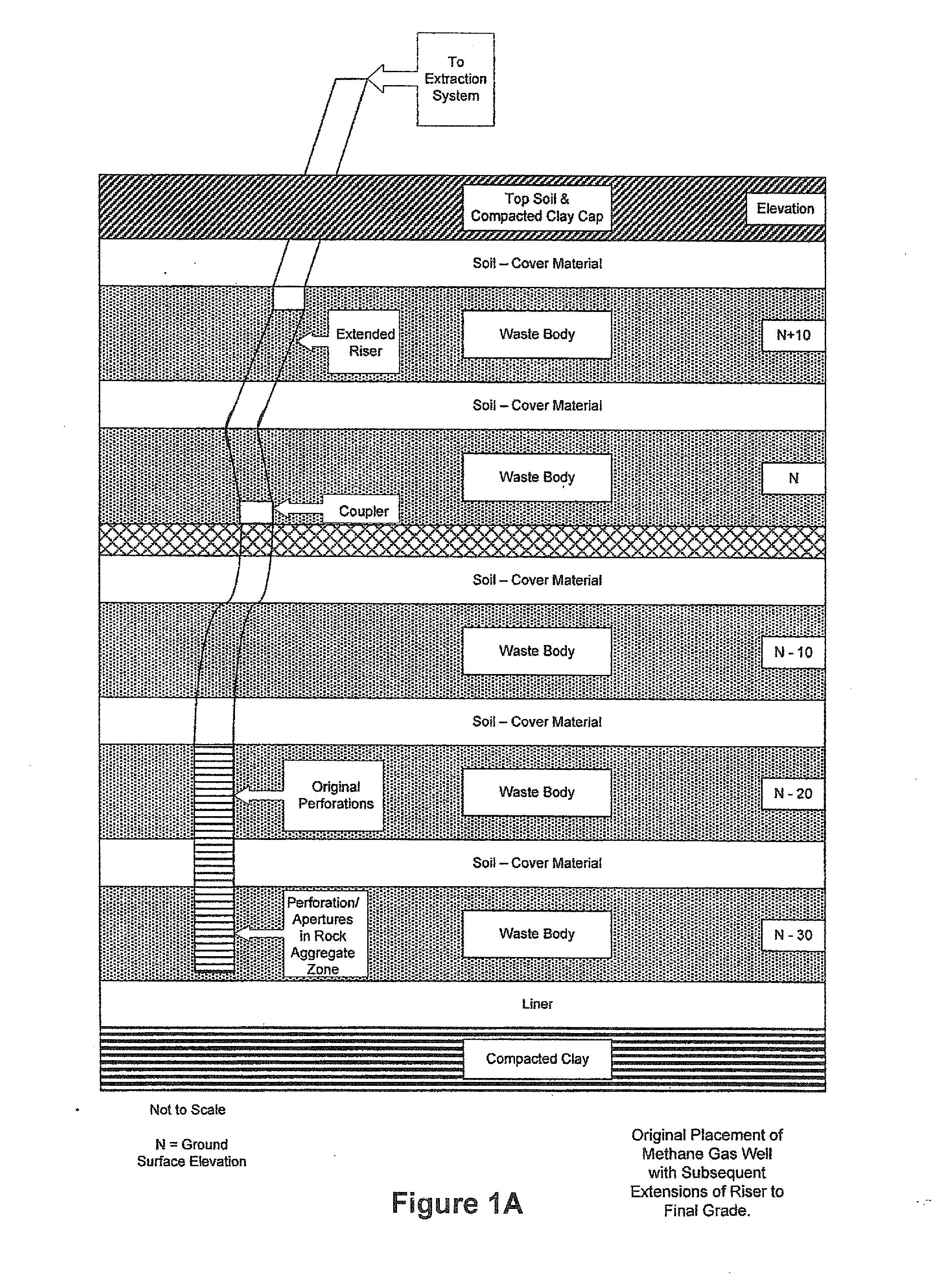
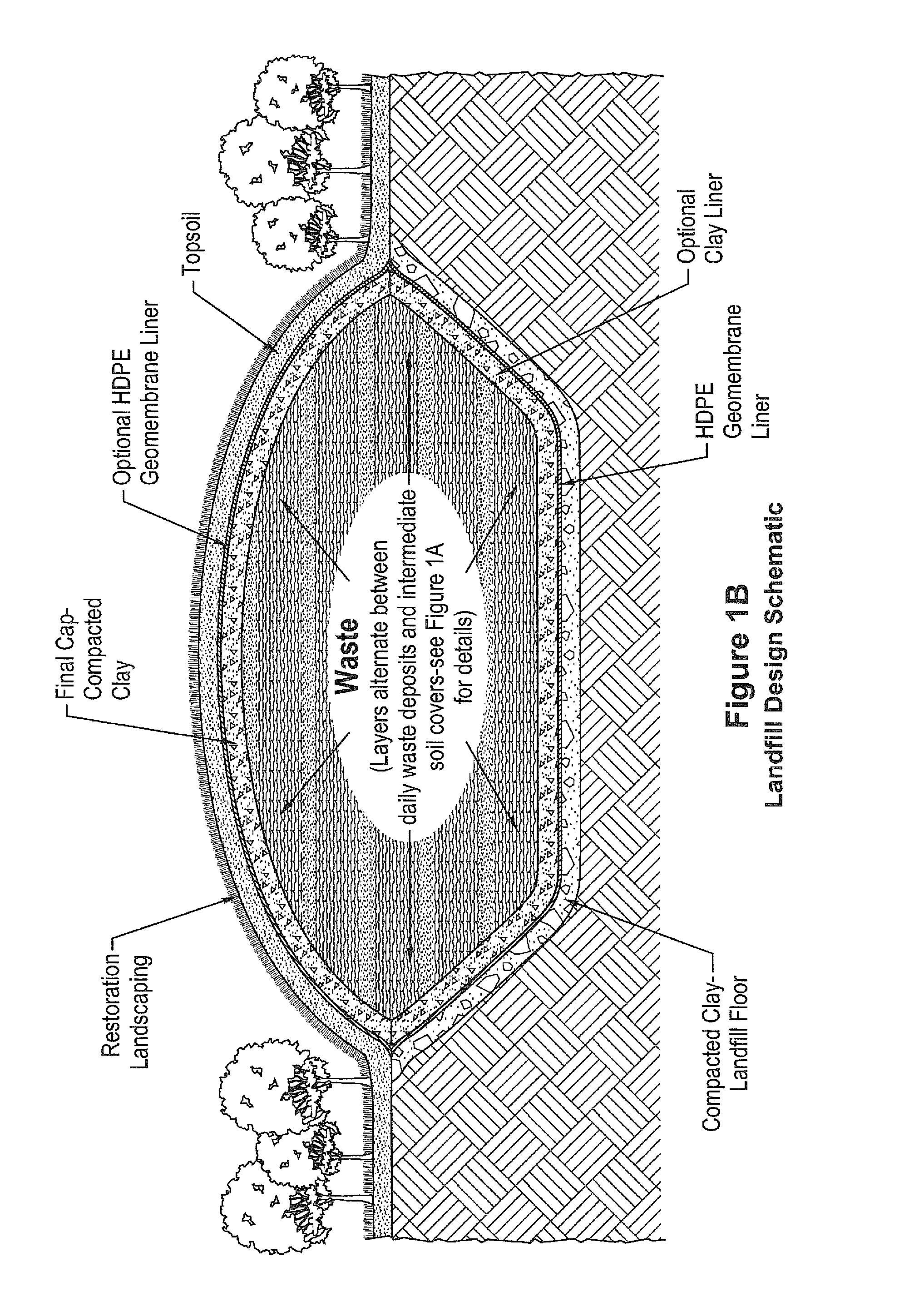
[0032]FIGS. 1A-1C are schematic depictions of landfills and the use of LFG recovery wells. The basic structure of a landfill includes a floor and sidewalls of compacted clay, typically covered with a high density polyethylene (HDPE) polymer liner. Another layer of clay is added to protect the inside of the layer. Layers of waste alternated with clay or soil layers covering the waste will be added to the empty landfill (See FIGS. 1A and 1B). Once a landfill has reached a certain capacity, LFG recovery wells are installed and LFG is extracted from decay and decomposition of waste layers. Generally, a LFG recovery well may be installed by the following method. A bucket auger rig is used to drill a borehole through the waste body. Perforated pipe / screen and riser are lowered into the borehole and set in place. Gravel or rock aggregate is introduced into the annular space between the pipe and the borehole via standard well installation techniques. The level of gravel or rock aggregate is...


PUM


Abstract

An apparatus and method to internally provide apertures inside polyvinyl chloride (PVC), high density polyethylene (HDPE), or any polymeric pie, plastic pipe-riser (blank casing) in existing landfill gas recovery wells (extraction wells) that have been installed at Municipal Solid Waste Facilities are described. By creating additional apertures in landfill gas recovery well risers, landfill gas derived from the decomposition of waste is allowed to enter the existing riser and extraction / recovery system. This process saves time and cost associated with drilling additional wells to capture landfill gas from subsequent layers of the waste body. The process assists in maintaining regulatory compliance by capturing landfill gas and preventing it from being emitted into the atmosphere.

Description

PRIOR RELATED APPLICATIONS[0001]This application is a continuation-in-part of U.S. patent application Ser. No. 12 / 558,203 filed on Sep. 11, 2009, which is incorporated by reference in its entirety.FEDERALLY SPONSORED RESEARCH STATEMENT[0002]Not applicable.REFERENCE TO MICROFICHE APPENDIX[0003]Not applicable.FIELD OF THE INVENTION[0004]The invention is a tool, system and method for providing openings or apertures internally through a polymeric pipe and a method of using the tool to improve landfill gas (LFG) extraction from LFG recovery wells at municipal solid waste facilities (MSWF). The method uses an internal pipe aperture tool to create openings or holes in existing riser pipe to extract additional LFG there through from LFG recovery wells at MSWF. By providing apertures in the LFG well riser pipes, the volume and rate of LFG extraction is enhanced, the amount of LFG extracted from a given landfill unit is increased and less LFG is emitted into the atmosphere. Increasing LFG cap...

Claims


Application Information

Patent Timeline
Patent Type & Authority Applications(United States)
IPC IPC(8): E21B43/00
CPCE21F7/00E21B43/112
Inventor STAMOULIS, STEFAN
Owner STAMOULIS STEFAN
Why Eureka
Try Eureka