Regenerative Braking System

Active Publication Date: 2011-08-18
GRAVINO MARC CHARLES
View PDF22 Cites 17 Cited by
  • Summary
  • Abstract
  • Description
  • Claims
  • Application Information

AI Technical Summary

Benefits of technology

[0022]In certain embodiments, incrementally storing includes compressing a spring in a first direction a plurality of times corresponding to a plurality of braking cycles. In certain embodiments, maintaining the stored energy includes preventing decompression of the spring in second direction opposite the first di

Problems solved by technology

Movement of the coupler in the second direction results in rotation of the elect

Method used


Image

  • Regenerative Braking System
  • Regenerative Braking System
  • Regenerative Braking System

Examples


Embodiment Construction

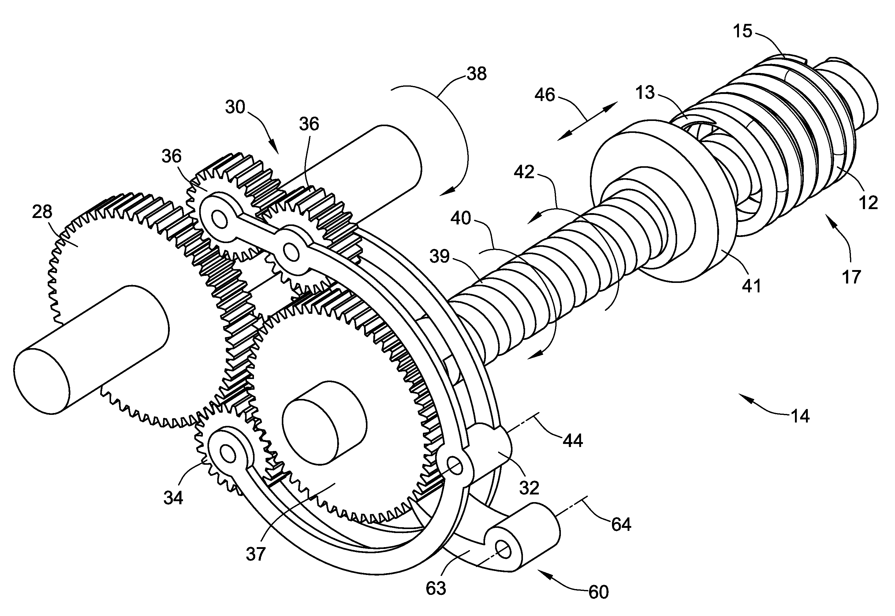
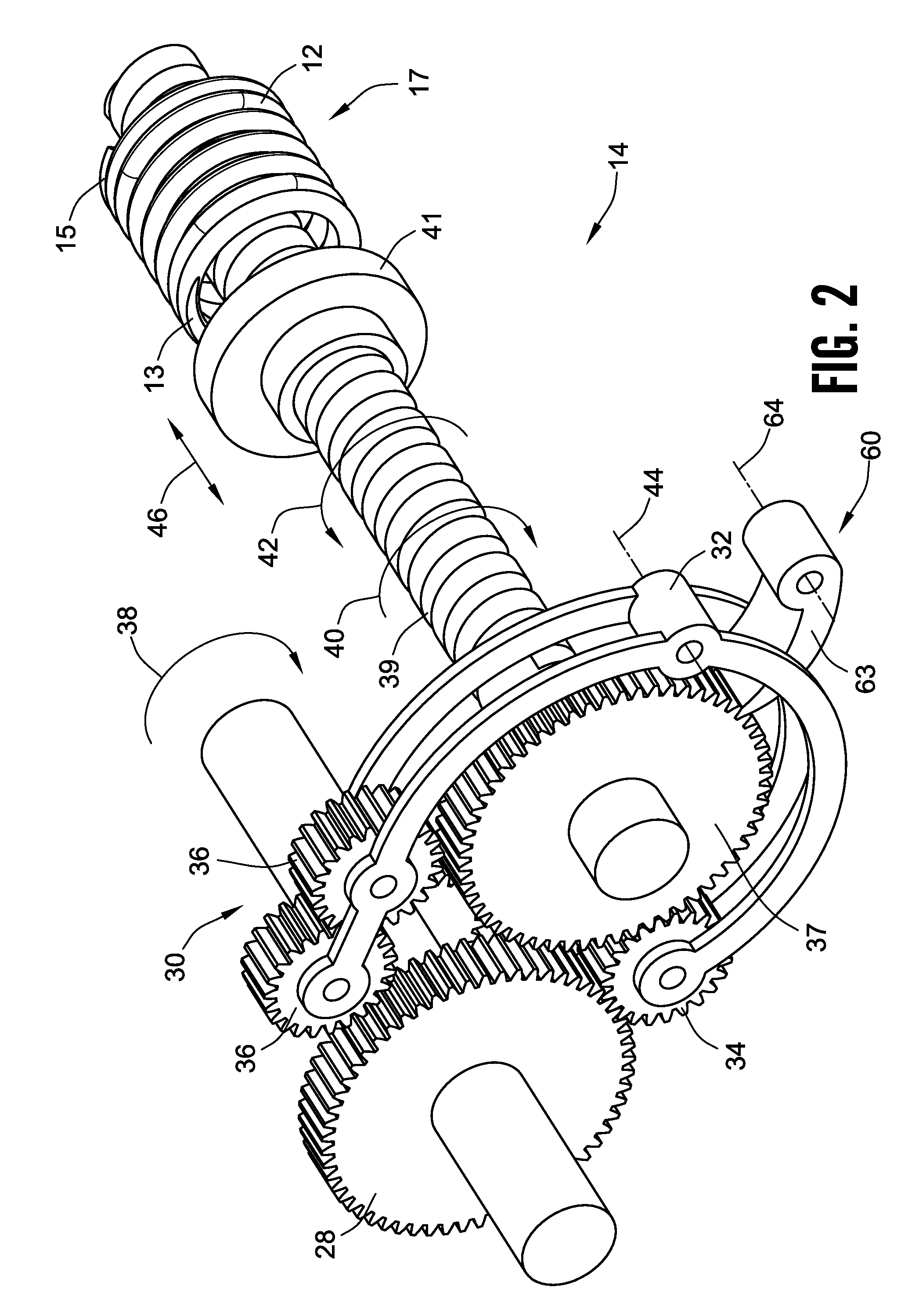
[0036]Turning now to the embodiments illustrated in FIGS. 1-10, a regenerative braking system will be described. It is recognized that the terms “motor vehicle” are used throughout the following description, the regenerative braking system is not limited to motorized vehicles only. Instead, the regenerative braking system can be incorporated into a variety of mechanical systems to selectively store and return surplus mechanical energy.

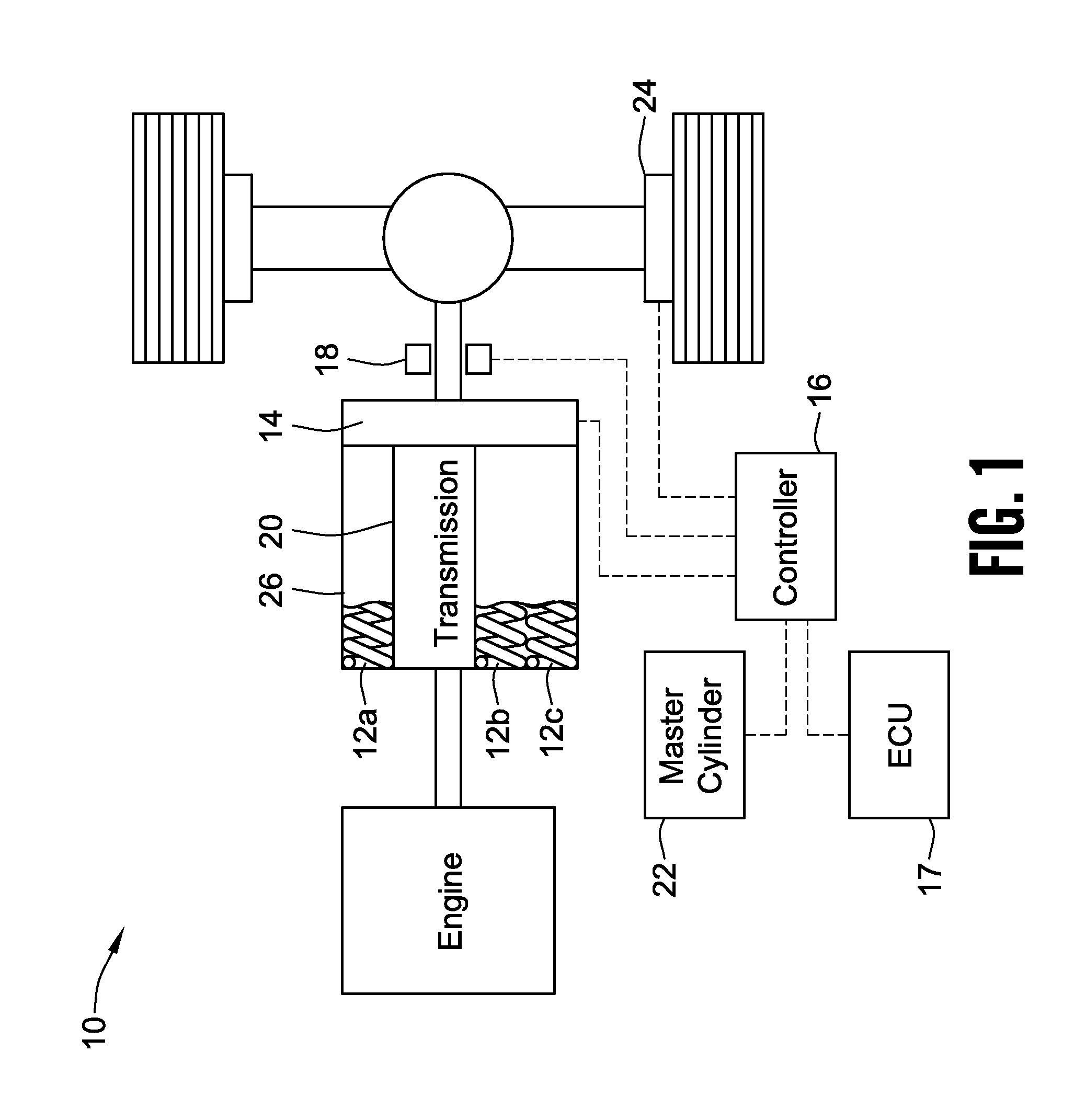
[0037]With reference now to the illustrated embodiment of FIG. 1, a regenerative braking system 10 is shown. The regenerative braking system 10 includes at least one compression spring 12a-c. It will be understood that although illustrated as incorporating multiple springs 12a-c, in other embodiments, a single spring 12 can be used. It will further be understood that although illustrated schematically as a compression spring, the springs 12a-c can take the form of other types of springs, such as for non-limiting example, leaf springs, coil springs, ten...


PUM


Abstract

A regenerative braking system is provided. The regenerative braking system includes at least one energy storage medium operably connected to a coupler. The coupler is operable to selectively couple and decouple the energy storage medium with a drive train of motor vehicle, or an electric generator, or a combination of both. A control arrangement governs the operation of the coupler. A sensor of the control arrangement is operable to determine information relating to the relative deceleration and acceleration of the motor vehicle and send said information to the controller. The controller is operable to determine the amount of energy storage medium or mediums to be coupled to the drive train via the coupler.

Description

CROSS-REFERENCE TO RELATED PATENT APPLICATIONS[0001]This patent application claims the benefit of U.S. Provisional Patent Application No. 61 / 304,089 filed Feb. 12, 2010, the entire teachings and disclosures of which are incorporated herein by reference thereto.FIELD OF THE INVENTION[0002]This present invention generally relates to an energy storage device for a vehicle, and more particularly to a regenerative braking system.BACKGROUND OF THE INVENTION[0003]In view of recent events, fuel economy for automotive vehicles has become of great importance. The rising cost of fuel and other considerations have driven manufactures of automotive vehicles to consider alternative fuel sources and systems such as hydrogen, solar power, fuel cells, hybrid gas / electric, and natural gas. Additionally, many hybrid vehicles combining various power transmission techniques have also been introduced to the market in recent years.[0004]A vehicle that utilizes an alternative fuel source provides the advan...

Claims


Application Information

Patent Timeline
IPC IPC(8): B60T1/10B60L11/16B60K8/00B60K6/10B60L50/30
CPCB60K6/10B60T1/10B60W10/184B60W10/24Y02T10/70B60L7/10B60L11/14B60L11/16Y02T10/6204B60W30/18127B60L50/16B60L50/30Y02T10/62
Inventor GRAVINO, MARC CHARLES
Owner GRAVINO MARC CHARLES
Why Eureka
Try Eureka