
Three-band antenna device with resonance generation and portable electronic device having the same

a three-band antenna and resonance generation technology, applied in the direction of antennas, antenna details, elongated active elements, etc., can solve the problems of inability to meet the consumers' expectations of compact size and the large size of multi-band antennas adapted for multi-frequency band wireless communication electronic devices, and achieve the effect of increasing the antenna siz

Inactive Publication Date: 2011-08-18
FIRST INTERNATIONAL COMPUTER
View PDF6 Cites 185 Cited by
  • Summary
  • Abstract
  • Description
  • Claims
  • Application Information

AI Technical Summary

Benefits of technology

[0008]The object of the present invention is to provide a three-band antenna device with resonance generation and a portable electronic device having the same, which can resonate to generate three frequency bands by two radiating elements without increasing antenna size.

Problems solved by technology

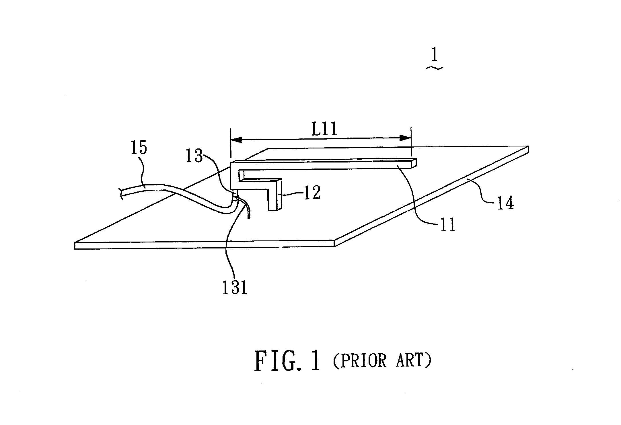
Thus, the size of a multi-band antenna adapted for multi-frequency band wireless communication electronic devices is too large, and thus cannot satisfy the consumers' expectation of compact size.

Method used


Image

  • Three-band antenna device with resonance generation and portable electronic device having the same
  • Three-band antenna device with resonance generation and portable electronic device having the same
  • Three-band antenna device with resonance generation and portable electronic device having the same

Examples


Embodiment Construction

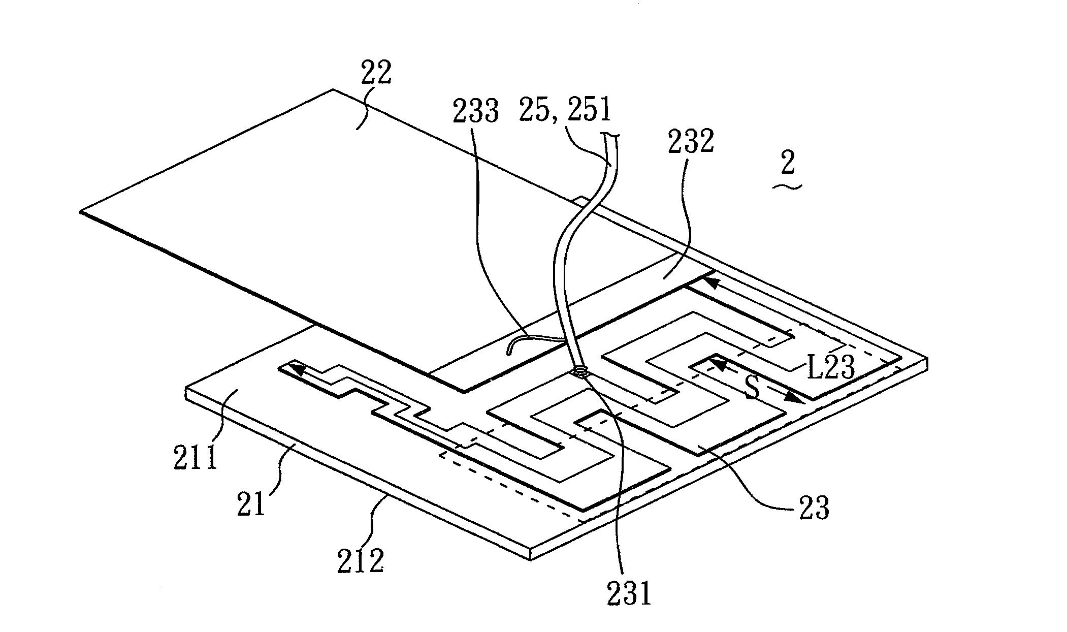
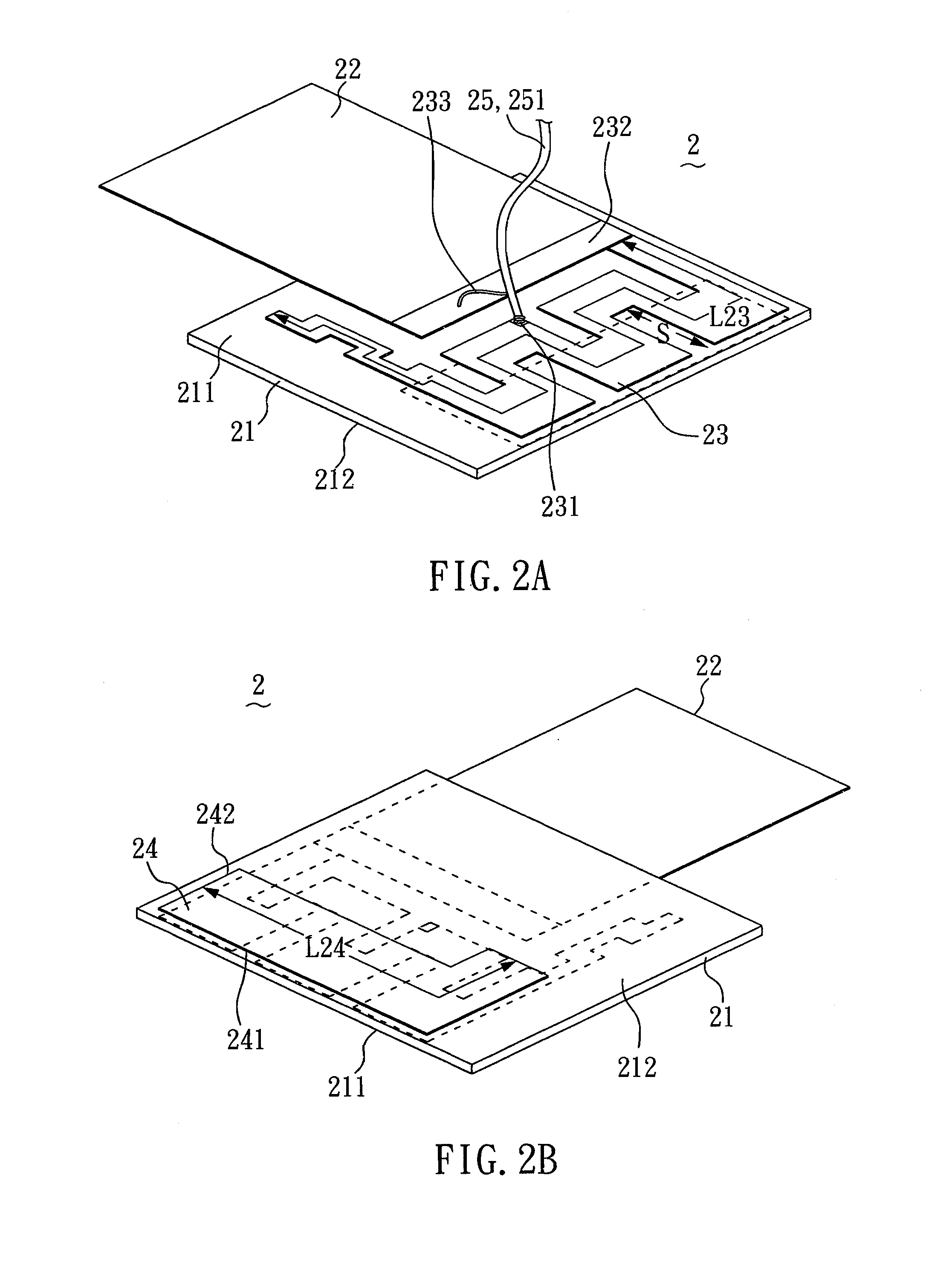
[0026]Please refer to FIGS. 2A and 2B. FIGS. 2A and 2B are perspective views of the first and second surfaces 211, 212 of the three-band antenna device 2 according to the invention. The three-band antenna device 2 comprises an isolating dielectric layer 21, a grounding element 22, a first radiating element 23, a second radiating element 24 and a feeding element 25. The isolating dielectric layer 21 is composed of non-conducting material, which can be a printed circuit board or air and is preferably a rectangular-shaped FR4 printed circuit board. The grounding element 22, the first radiating element 23 and the second radiating element 24 are preferably thin metal films. The isolating dielectric layer 21 includes the first and second surfaces 211, 212. The first radiating element 23 installed on the first surface 211 sets up a feeding part 231 and a grounding part 232 on it, and the grounding part 232 is preferably connected the grounding element 22. The second radiating element 24 is...


PUM


Abstract

A three-band antenna device with resonance generation includes a dielectric layer having an upper surface and a lower surface, a grounding element, a first radiating element, and a second radiating element. The first radiating element is arranged on the upper surface for providing a first frequency band. The second radiating element is arranged on the lower surface and stacked below the first radiating element via the dielectric layer for providing a second frequency band, so as to generate a parasitic capacitance therebetween. A third frequency band is provided by the resonance of the parasitic capacitance and the parasitic inductance in the second radiating element.

Description

BACKGROUND OF THE INVENTION[0001]1. Field of the Invention[0002]The present invention relates to a three-band antenna device with resonance generation and, more particularly, to a three-band antenna device capable of transmitting and receiving signals in three different frequency bands simultaneously without increasing the antenna size.[0003]2. Description of Related Art[0004]Recently, electronic devices with wireless communication capabilities have become more and more popular, many different types of communication protocols have been formulated, and many frequency bands can be used. Thus, the frequency band of the internal antennas installed in electronic devices, such as notebook computers, should cover many different frequency bands for different wireless communication protocols.[0005]Since planar inverted-F antenna (PIFA) has advantages such as simple structure, convenient production, easy integration, low profile, good performance and small size, it is widely applied in portab...

Claims


Application Information

Patent Timeline
Patent Type & Authority Applications(United States)
IPC IPC(8): H01Q1/38H01Q5/10
CPCH01Q1/2266H01Q5/378H01Q9/42
Inventor LIN, HSIAO-KUANGCHANG, YU-CHENGCHANG, CHIH-CHUN
Owner FIRST INTERNATIONAL COMPUTER
Learn More