Liquid Crystal Display Device

a liquid crystal display and display device technology, applied in the direction of identification means, instruments, coatings, etc., can solve the problem of insufficient suppression of coloring, and achieve the effect of ensuring visibility and reducing coloring

Inactive Publication Date: 2011-08-18
SHARP KK
View PDF6 Cites 25 Cited by
  • Summary
  • Abstract
  • Description
  • Claims
  • Application Information

AI Technical Summary

Benefits of technology

[0032]According to the liquid crystal display device of the present invention, visibility can be ensured and coloring can be decreased regardless of the direction of the screen, even if the screen is viewed through an optical member having a polarization function, such as polarized sunglasses.

Problems solved by technology

But a retarder material which implements an ideal inverse wavelength dispersion has yet to be developed, so sufficiently suppressing coloring is difficult.

Method used


Image

  • Liquid Crystal Display Device
  • Liquid Crystal Display Device
  • Liquid Crystal Display Device

Examples


embodiment 1

(Liquid Crystal Display Device)

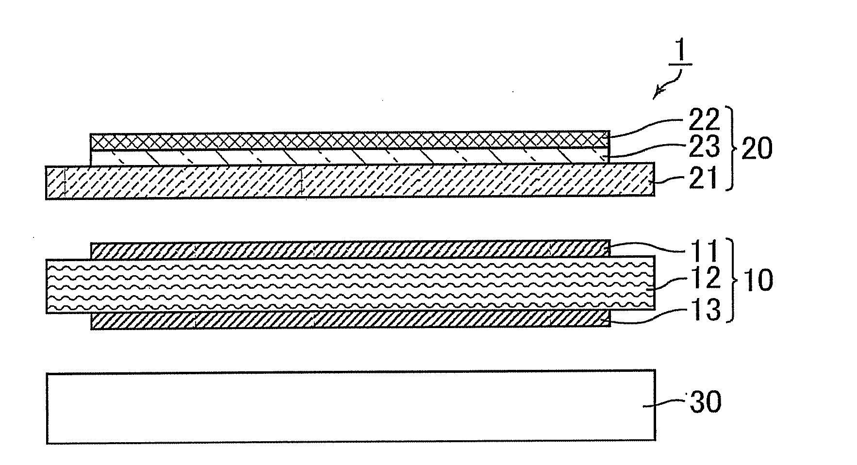
[0046]A liquid crystal display device 1 is a transmissive liquid crystal display device as shown in FIG. 1, and has a back light unit 30, a liquid crystal display panel 10 which is disposed at the emission surface side of the back light unit 30, and a front plate 20 which is disposed at the observation surface side of the liquid crystal display panel 10.

[0047]The liquid crystal display panel 10 has a liquid crystal cell 12, a polarizing element 11 (corresponds to the first polarizing element) glued to the observation surface of the liquid crystal cell 12 with acrylic adhesive, and a polarizing element 13 (corresponds to the third polarizing element) glued to the rear face of the liquid crystal cell 12 with acrylic adhesive.

[0048]The front plate 20 has a protective plate 21, an optical anisotropic layer 23 which is glued to the front face of the protective plate 21 with acrylic adhesive, and a polarizing element 22 (corresponds to the second polarizing ...

example 1

(Fabrication of Quarter-Wave Plate)

[0105]A long retardation film (quarter-wave plate) was created by uniaxially stretching the long cyclic polyolefine resin film (made by Zeon Corp., product name: Zeonoa film) to be 1.52 times between rolls having different circumferential speeds at 140° C. The thickness of this film was 35 μm, and the in-plane retardation Re was 139 nm.

(Fabrication of Front Plate)

[0106]The obtained quarter-wave plate was glued together with a commercial polarizer (made by Nitto Denko Corp., product name: SEG 1224DU) with an adhesive layer therebetween. At this time, the angle formed by the slow axis of the quarter-wave plate and the absorption axis of the polarizer was set to be 45°. This polarizer had a structure of an iodine polarizing film being interposed between two TACs.

[0107]The obtained polarizer with the quarter-wave plate was attached to a glass substrate which was a protective plate. Here the absorption axis of the polarizer was set to make a 45° angle w...


PUM

PropertyMeasurementUnit
wavelengthaaaaaaaaaa
reflectionaaaaaaaaaa
sizesaaaaaaaaaa

Abstract

The present invention provides a liquid crystal display device which can ensure visibility and decrease coloring regardless of the direction of the screen, even if the screen is viewed through an optical member having a polarization function, such as polarized sunglasses. In at least one embodiment, a liquid crystal display device includes: a liquid crystal cell; and a first polarizing element disposed at an observation surface side of the liquid crystal cell, and the liquid crystal display device further includes a second polarizing element disposed at the observation surface side of the first polarizing element. It is preferable that the liquid crystal display device further includes a protective plate disposed between the first polarizing element and the second polarizing element.

Description

TECHNICAL FIELD[0001]The present invention relates to a liquid crystal display device, and more particularly to a liquid crystal display device which is suitably used for an application where displayed images are viewed in a state of wearing polarized sunglasses.BACKGROUND ART[0002]Recently the screen sizes of liquid crystal display devices are increasing, and liquid crystal devices are now used for various applications, including large screen TVs. In particular, application as a display device for outdoor environments, such as a digital signage, is receiving attention.[0003]In the case of such a liquid crystal display device used in outdoor environments, a viewer may view the screen in a state of wearing polarized sunglasses to prevent glare from outdoor light. A liquid crystal display device normally displays images using polarizing elements, and light transmitting through the polarizing elements at the front face side is emitted to viewers, therefore emitted light is linearly pol...

Claims


Application Information

Patent Timeline
Patent Type & Authority Applications(United States)
IPC IPC(8): G02F1/1335G02B1/11G02B1/118G02B1/14G02B5/30G02F1/13363G09F9/00
CPCG02B1/118G02B5/30G02F2001/133638G02F1/13363G02F2001/133531G02F1/133528G02F1/133531G02F1/133638
Inventor HASEGAWA, MASAHIROSAKAI, AKIRA
Owner SHARP KK
Why Eureka
Try Eureka