Castor wheel construction for furniture pieces and the like

Active Publication Date: 2011-08-25
O G T M OFF MEC
View PDF12 Cites 13 Cited by
  • Summary
  • Abstract
  • Description
  • Claims
  • Application Information

AI Technical Summary

Benefits of technology

[0034]Another object of the present invention is to provide such a castor wheel construction which does not require to use sliding elements, such as sliding bearings.
[0035]Yet another object of the present invention is to provide such a castor wheel construction which operates in a very efficient manner for a very long operating time.
[0036]Yet another object of the present invention is to provide such a castor wheel construction which, owing to its specifically designed structural features, is very reliable and safe in operation.
[0037]Another object of the present invention is to provide such a castor wheel construction which can be made starting from easily commercially available elements and materials and which, moreover, is very competitive from a mere economic standpoint.

Problems solved by technology

The individual or single wheel element castor wheels have the disadvantage that they provide a resistance against a rotary movement of the wheel assembly about the vertical axis, thereby the movement of the furniture piece or trolley the wheel assembly is applied to cannot be considered an even movement.
Moreover, the wheel element central rotary axis is clamped outside of the wheel element by clamping or support members which are not protected with respect to possible impacts against articles such as other furniture pieces or walls.
Such an impact could damage the wheel assembly axis, thereby decreasing the operating efficiency of the wheel assembly, or making a proper operation impossible.
Moreover, in the double wheel element system, the wheel element axis support is arranged at the center of the support assembly and between the two wheel elements for protecting them from possible impacts and damages, thereby causing a consequent driving efficiency decrease.
A main problem of the above two wheel element assembly is that of properly clamping the wheel elements to the central axis.
This connecting or clamping system is not efficient as desired, since it has a very low stability: in fact, since the axis does not pass through the wheel element, the wheel element load on said axis is an asymmetrical one, and being maximum near the wheel element inner part joined to the axis and minimum, or zero, outside of the wheel element.
Such instability generates, as it should be easily apparent from an examination of a wheel assembly of the second type, a great clearance between the wheel elements and central axis, which not only causes the wheel assembly to inefficiently operate, but which, moreover, negatively affects the aesthetic aspect of the overall furniture piece or trolley the wheel assembly is connected to.
Both the above disclosed castor wheel types, moreover, have further substantial drawbacks.
Due to the above reasons, upon a long use of the wheel assembly, friction will progressively remove material from the hole thereby enlarging the latter, to provide an instable rotary movement on the wheel on its axis, with a consequent inefficient operation of the overall wheel assembly.
Moreover, in a condition in which the rotary of a wheel element is a comparatively slow one and the main function of the wheel element is that of supporting a comparatively large load, then the use of a central rotary axis does not constitute the most efficient approach.
Such a torque provides an additional load on the wheel element / axis assembly, thereby further decreasing the operating stability of the overall wheel assembly.
From the above it occurs that, for making a hubless castor wheel, it is necessary to form the above mentioned recesses, with a comparatively high machining precision, causing in turn an increase of the making and selling cost of such a hubless castor wheel.
Moreover, in a long operation time, the sliding elements tend to damage the recessed contours to enlarge them, and correspondingly enlarging the clearance between the annular inner element and toroidal wheel, thereby decreasing the stability of the overall wheel assembly.

Method used


Image

  • Castor wheel construction for furniture pieces and the like
  • Castor wheel construction for furniture pieces and the like
  • Castor wheel construction for furniture pieces and the like

Examples


Embodiment Construction

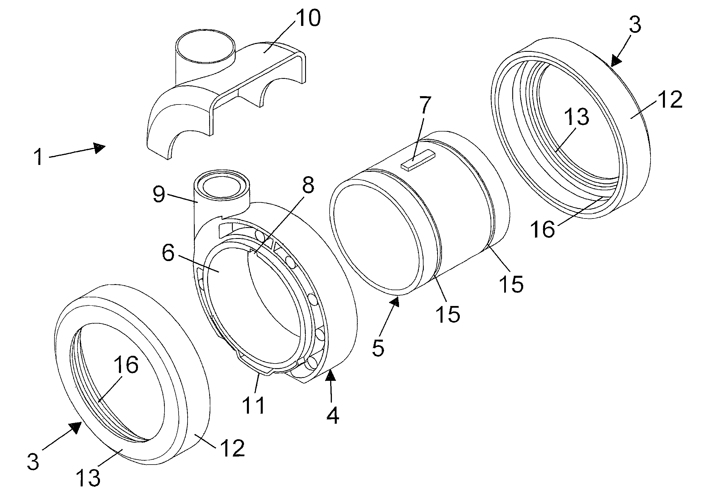
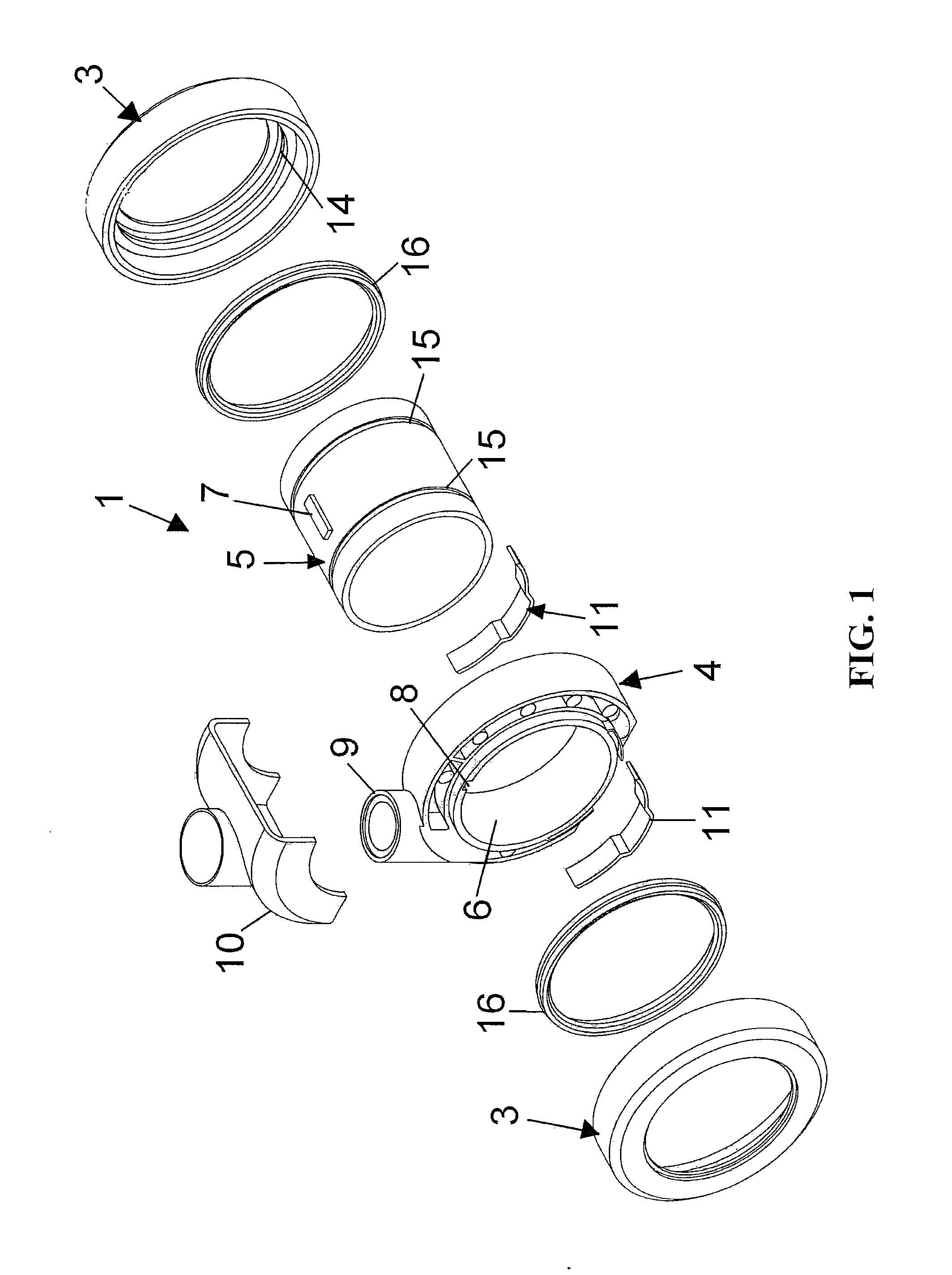
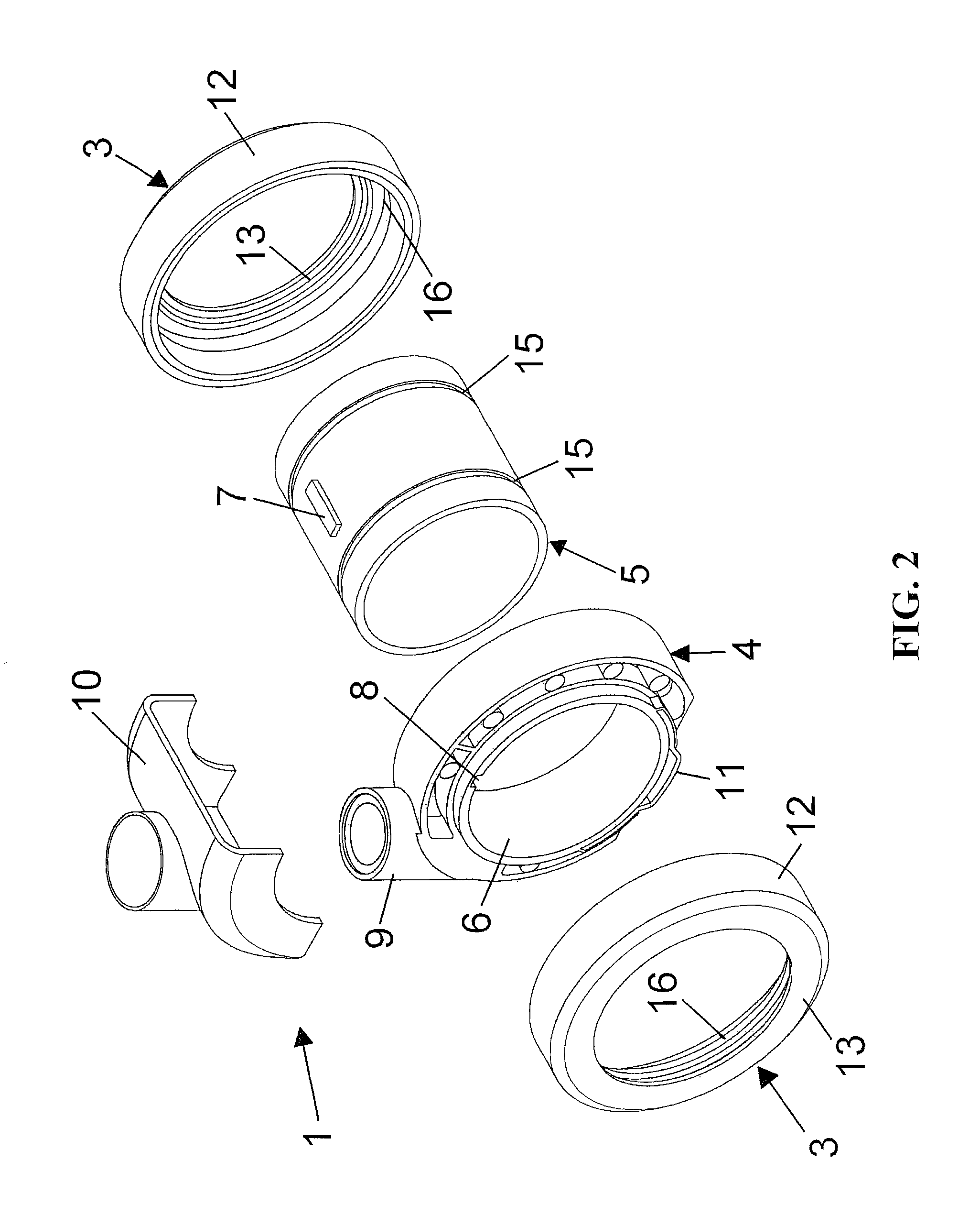
[0046]With reference to the number references of the above mentioned figures, the castor wheel construction according to the present invention, generally indicated by the reference number 1, comprises a castor wheel hub 2 supporting a pair of wheels 3.

[0047]The castor wheel hub 2 comprises an annular support 4 supporting a cylinder 5 having two end portions thereon the two wheels 3 are mounted.

[0048]The annular support 4 comprises moreover a cylindric recess or seat 6 receiving the cylinder 5 which is advantageously provided with a ridge portion 7, which may be fixedly engaged in a longitudinal seat or recess 8 formed on the surface of the cylindric seat for preventing the cylinder 5 from turning with respect to the annular support.

[0049]Said annular support 4 comprises moreover a vertical attachment portion 9, for receiving a peg or other like element, integral with the furniture piece or other component the castor wheel construction must be coupled to.

[0050]The peg, not shown in t...


PUM


Abstract

A castor wheel construction for furniture pieces and the like comprises a hub including an annular supporting element supporting a cylinder having two end portions thereon two wheels are respectively mounted, one for each cylinder portion, the annular supporting element also including a vertical attachment portion for receiving a peg element integral with the furniture pieces, to allow the castor wheel construction to turn about a vertical axis, each wheel comprising a cylindric portion operating as a tread, coupled to a flange portion, the wheels being fixedly coupled to the cylindric portion.

Description

BACKGROUND OF THE INVENTION[0001]The present invention relates to a castor wheel construction, particularly designed for furniture pieces and the like.[0002]As is known, swinging or castor wheels are conventionally used for allowing furniture pieces such as chairs, tables, desks and carriages, as well as shop trolleys, to be easily handled.[0003]Prior castor wheels may be classified as included substantially into two classes, that is a single wheel type or a double wheel element type.[0004]In a single wheel element castor wheel, a single wheel element has a rotary axis cooperating with a support element which, in turn, is clamped or connected to a furniture piece or a trolley, by a vertically extending connecting pin.[0005]This connecting pin allows the castor wheel to rotate about a substantially vertical axis, thereby allowing the furniture piece or trolley to be driven in any desired direction.[0006]The individual or single wheel element castor wheels have the disadvantage that t...

Claims


Application Information

Patent Timeline
IPC IPC(8): B60B33/00
CPCB60B33/0028B60B33/0042B60B33/0049B60B33/0057Y10T16/1853B60B33/0073Y10T16/184Y10T16/195B60B33/0068A47B91/06B60B33/00B60B33/02
Inventor TRIVINI, RUGGERO
Owner O G T M OFF MEC
Why Eureka
Try Eureka