
Control system for power-assisted door

Active Publication Date: 2011-08-25
TRI MARK CORP
View PDF42 Cites 60 Cited by
  • Summary
  • Abstract
  • Description
  • Claims
  • Application Information

AI Technical Summary

Benefits of technology

[0005]It is a primary object, feature, or advantage of the present invention to improve over the state of the art.
[0006]It is a further object, feature, or advantage of the present invention to provide a control system for a power-assisted door which is flexible and versatile.
[0007]It is a still further object, feature, or advantage of the present invention to provide a control system for a power-assisted door which is capable of use in a military vehicle.
[0008]Yet a still further object, feature, or advantage of the present invention is to provide a control system for a power-assisted door which allows for intuitive motion control system for heavy, power assisted, vehicle doors and ramps.
[0009]A still further object, feature, or advantage of the present invention to provide a control system for a power-assisted door which simplifies a soldier's ingress and egress from heavily armored vehicles that require power assisted opening and closing of doors.
[0010]Another object, feature, or advantage of the present invention is to provide a control system which may be used with a vehicle door having an intuitive joystick control system for locking, unlocking, latching, unlatching, opening and closing the door or ramp.

Problems solved by technology

While necessary to protect military personnel, heavier armor creates unique problems.
Prior art powered doors require separate mechanical and electrical systems, with separate control handles for the door and locks, which result in non-integrated and complicated door functions.
These complications necessarily lead to increased difficulties and time in opening and closing the heavy doors of these armored vehicles, particularly in emergency situations.
Yet, attempting to simplify the manner in which a user may use a power-assisted door can significantly complicate its design.
For example, high power transfer function is needed to provide motion to these substantial doors, yet only limited power is available in the vehicle (especially when the alternator is not charging the system) thus, there is a need to accommodate special design considerations for lower idle current draw as well as redundant backup battery charging.

Method used


Image

  • Control system for power-assisted door
  • Control system for power-assisted door
  • Control system for power-assisted door

Examples


Embodiment Construction

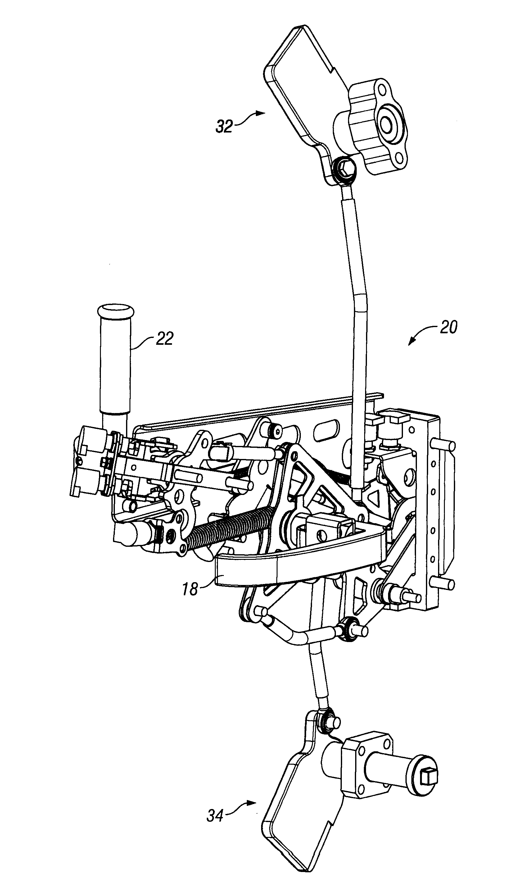
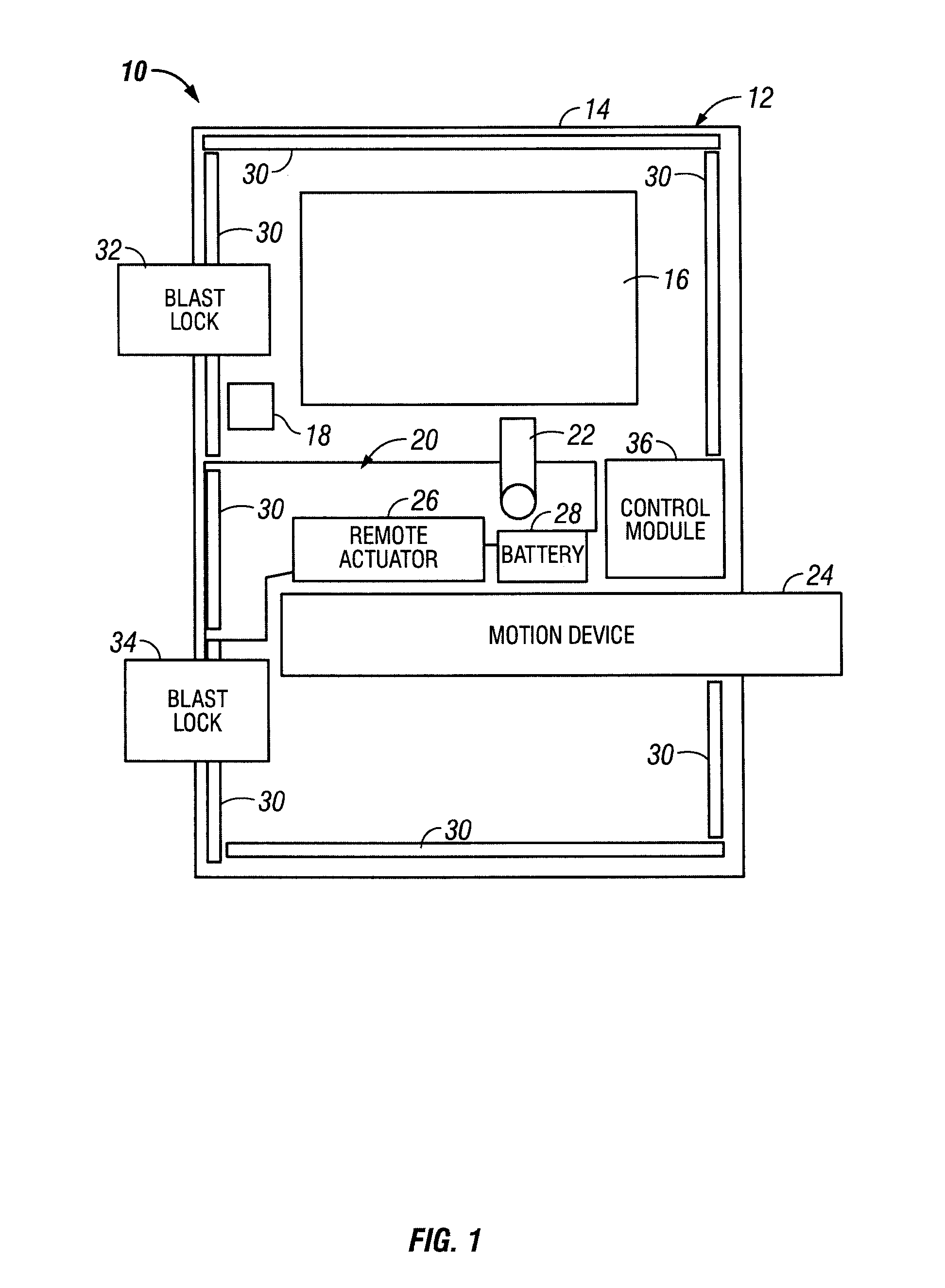
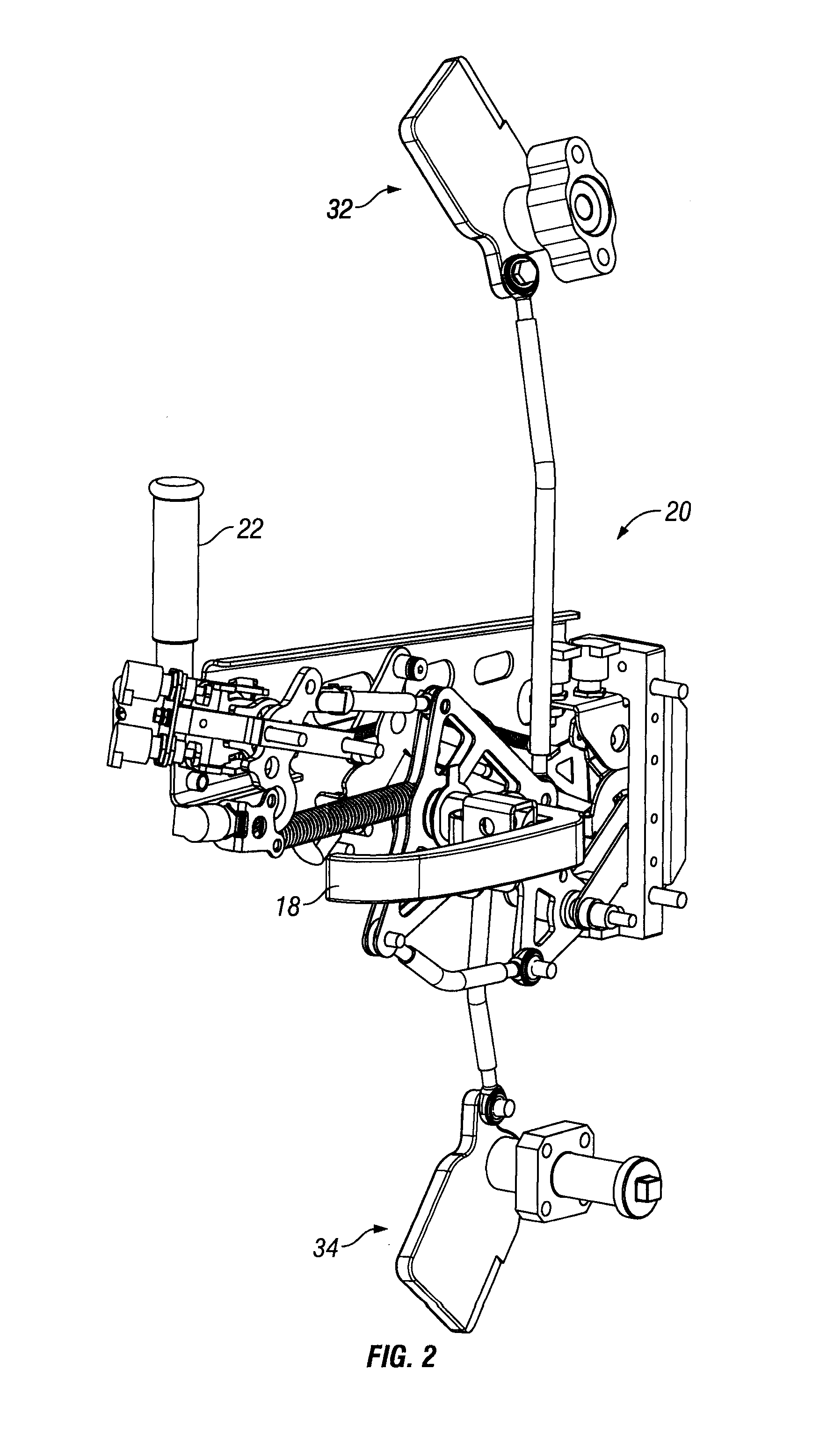
[0026]The present invention provides an electronic module which may be used to control functions doors requiring power assist. The module complements other mechanical features of said door. The specific features of the door include, without limitation, locking, unlocking, door opening, door closing. Although the term “door” is used here, it is to be understood to broadly refer to structure which provides access to access openings which, in some cases, may be alternatively referred to as ramps or hatches depending upon the specific application. For purposes of explanation, here the door is described with respect to a heavy door or ramp of an armored military vehicle with power assist and an intuitive control system. The present invention is not, however, to be limited to this specific application. In fact, as will later be described herein, the electronic module is very versatile and highly customizable. As such, the electronic module may be used in a variety of different application...


PUM


Abstract

A control system for a power assisted door, the electronic door control system includes an intelligent control, a plurality of sensor inputs operatively connected to the intelligent control, the plurality of sensor inputs associated with state of a plurality of mechanical components of the power assisted door, and a power drive operatively connected to the intelligent control for providing opening and closing of the power assisted door. The intelligent control is configured to monitor status of the plurality of sensor inputs and control the power drive at least partially based on the status of the plurality of sensor inputs. The intelligent control may be adapted to determine when state of the plurality of sensor inputs is indicative of one or more conditions which would preclude safe door movement. A power distribution module may also be present to assist in limiting current draw and to allow for charging.

Description

FIELD OF THE INVENTION[0001]The present invention relates to access openings, such as, without limitation, doors hatches, ramps, etc. More specifically, but not exclusively, the present invention relates to an electronic door control module for use in doors which use power assist.BACKGROUND OF THE INVENTION[0002]To assist in providing background of the present inventions, issues associated with heavy duty armored vehicles are discussed. Although the present invention may be used in such applications, the present invention is not to be limited to this particular application, as it is contemplated that the present invention may be used with other types of vehicles or stationary structures.[0003]Heavy duty armored vehicles, used for example, by the military, must be built to withstand forces far greater than encountered by conventional consumer cars and trucks. The utilization of increasingly powerful explosive devices such as IED's, RPG's, and EFP's by hostile insurgent forces has com...

Claims


Application Information

Patent Timeline
IPC IPC(8): E05F15/02B60J5/04E06B3/70H02P7/00H02J7/00G08C19/16
CPCE05Y2400/512E05Y2400/612E05Y2900/504G08C17/00G08C2201/51E05F15/603H02J7/00H02J7/1423E05F15/42E05F15/50E05B83/01
Inventor MAGNER, DAVID S.BERGMAN, JOHN TODD
Owner TRI MARK CORP
Learn More