Pressure regulator for shock absorber valve

a technology of pressure regulator and shock absorber valve, which is applied in the direction of springs, vibration dampers, springs/dampers, etc., can solve the problems of difficulty in achieving the desired low damping level of low speed and small valve flow, and achieve the effect of further restricting the flow of damping medium and increasing damping

Active Publication Date: 2011-08-25
OHLINS
View PDF7 Cites 19 Cited by
  • Summary
  • Abstract
  • Description
  • Claims
  • Application Information

AI Technical Summary

Benefits of technology

[0025]In a further embodiment, a further damping of the motion of the first valve part is created by the arrangement of at least one damping hole in the inner spr

Problems solved by technology

Such extreme accuracy per se leads to a more expensive production process, but still has lower costs compared with the accuracy which is demanded in the process if low bias is to be achieved with just a stiff spring.
Due to this noise problem and difficulties with the accuracy for the length tolerances of springs, pressure regulators including only one spring, for

Method used


Image

  • Pressure regulator for shock absorber valve
  • Pressure regulator for shock absorber valve
  • Pressure regulator for shock absorber valve

Examples


first embodiment

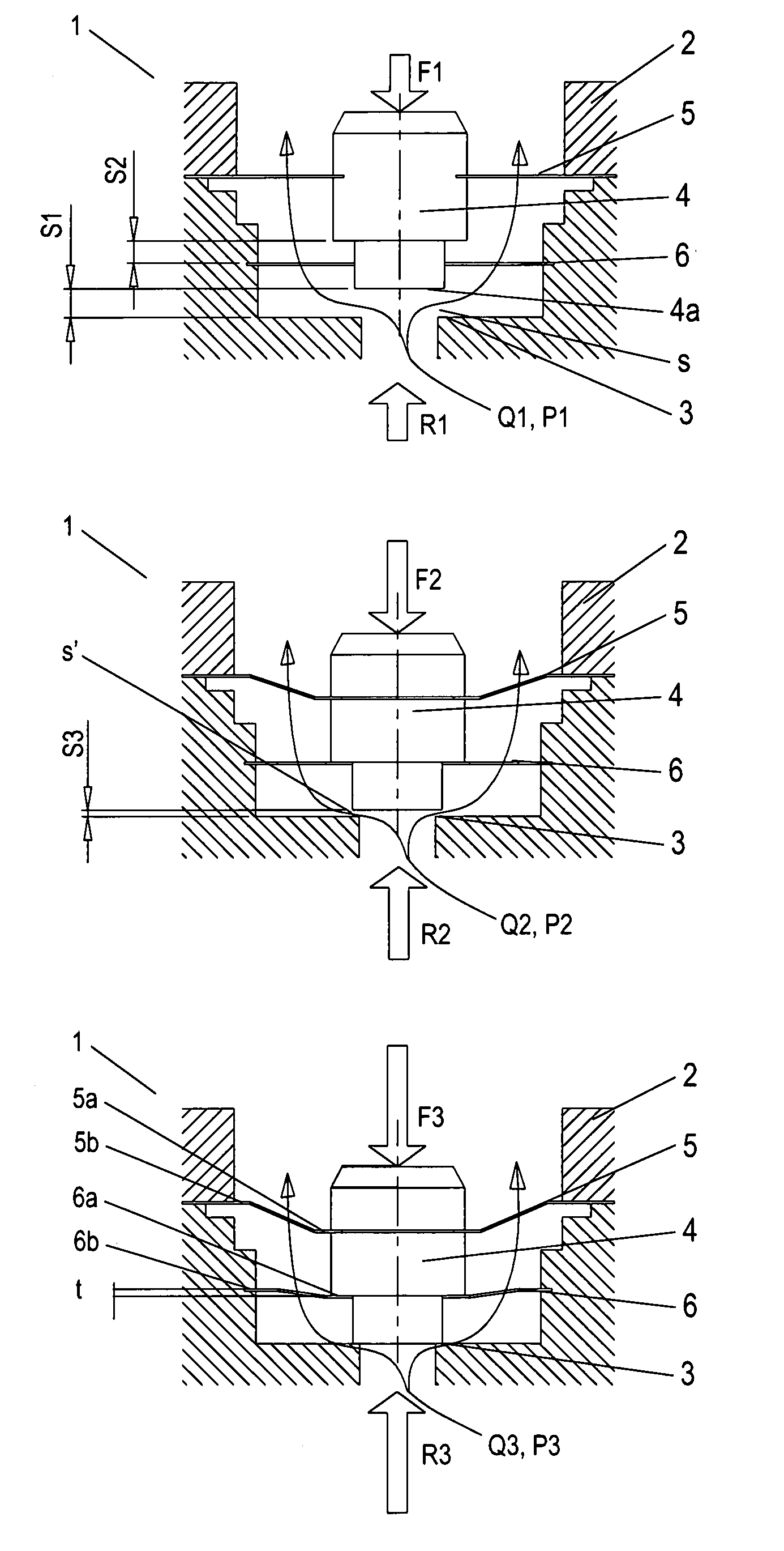
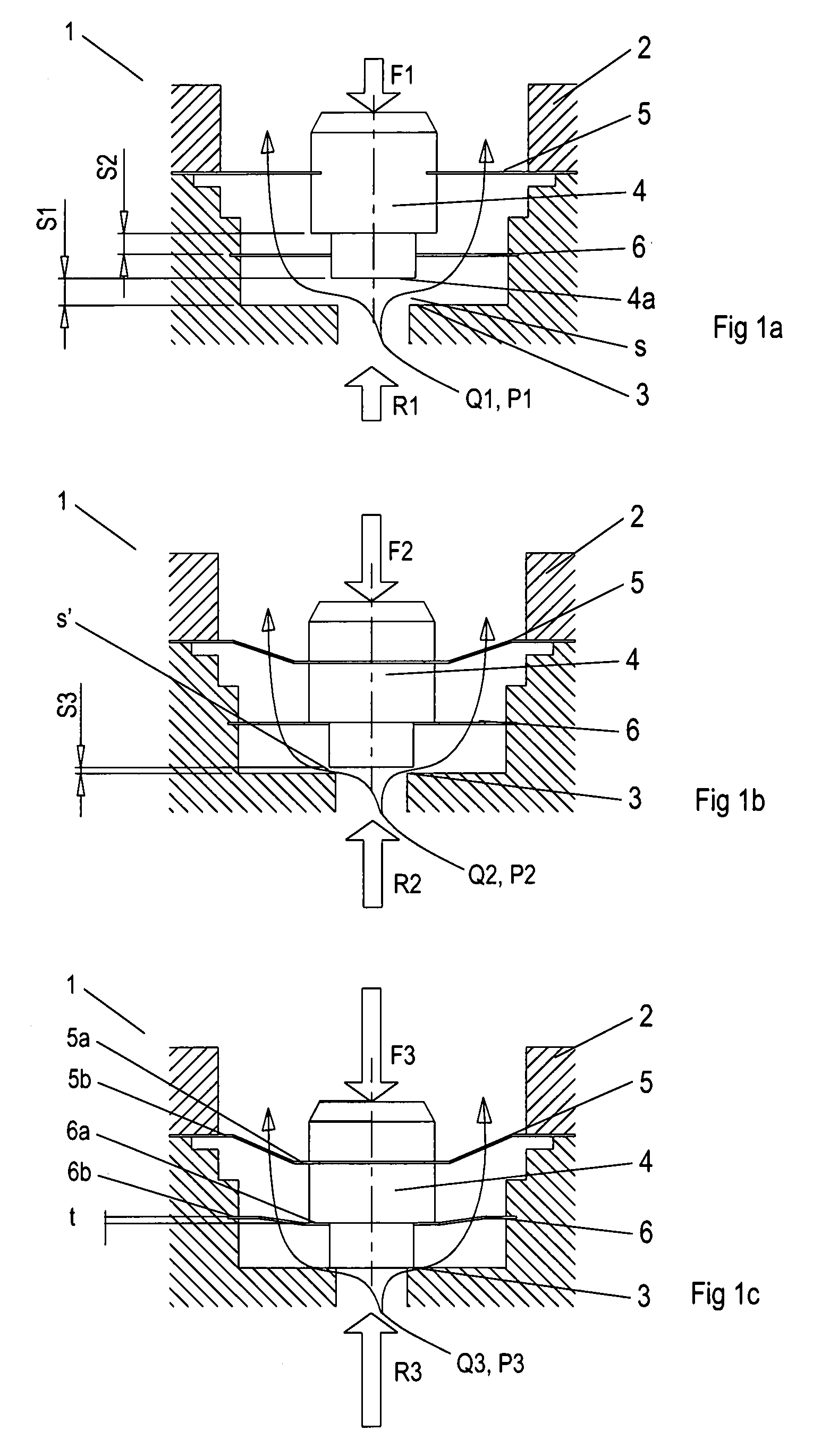
[0044]In the first embodiment in FIGS. 1a-1c, the springs 5, 6 are of the shim type, see also FIG. 4a, 4b. They are thus produced from a thin, circular washer and are configured with an outer 5b, 6b and an inner 5a, 6a spring part which are mutually connected with resilient bridges 5d, 6d, so that the outer and the inner spring part can spring relative to each other. Between the bridges 5d, 6d and the respective spring part, flow-through holes 5c, 6c are created, which to a certain extent restrict the flow q through the spring 5, 6. A parallel displacement t of the inner spring parts 5a, 6a of the springs is created by the outer spring part 5b, 6b being fastened in a part of the valve housing 2 and by the inner spring part 5a, 6a being fixed in or resting on the axially movable first valve part 4. The parallel displacement can also be realized by the inner spring part being fastened in a part of the valve housing and the outer part being fixed in or resting on the movable first valv...

second embodiment

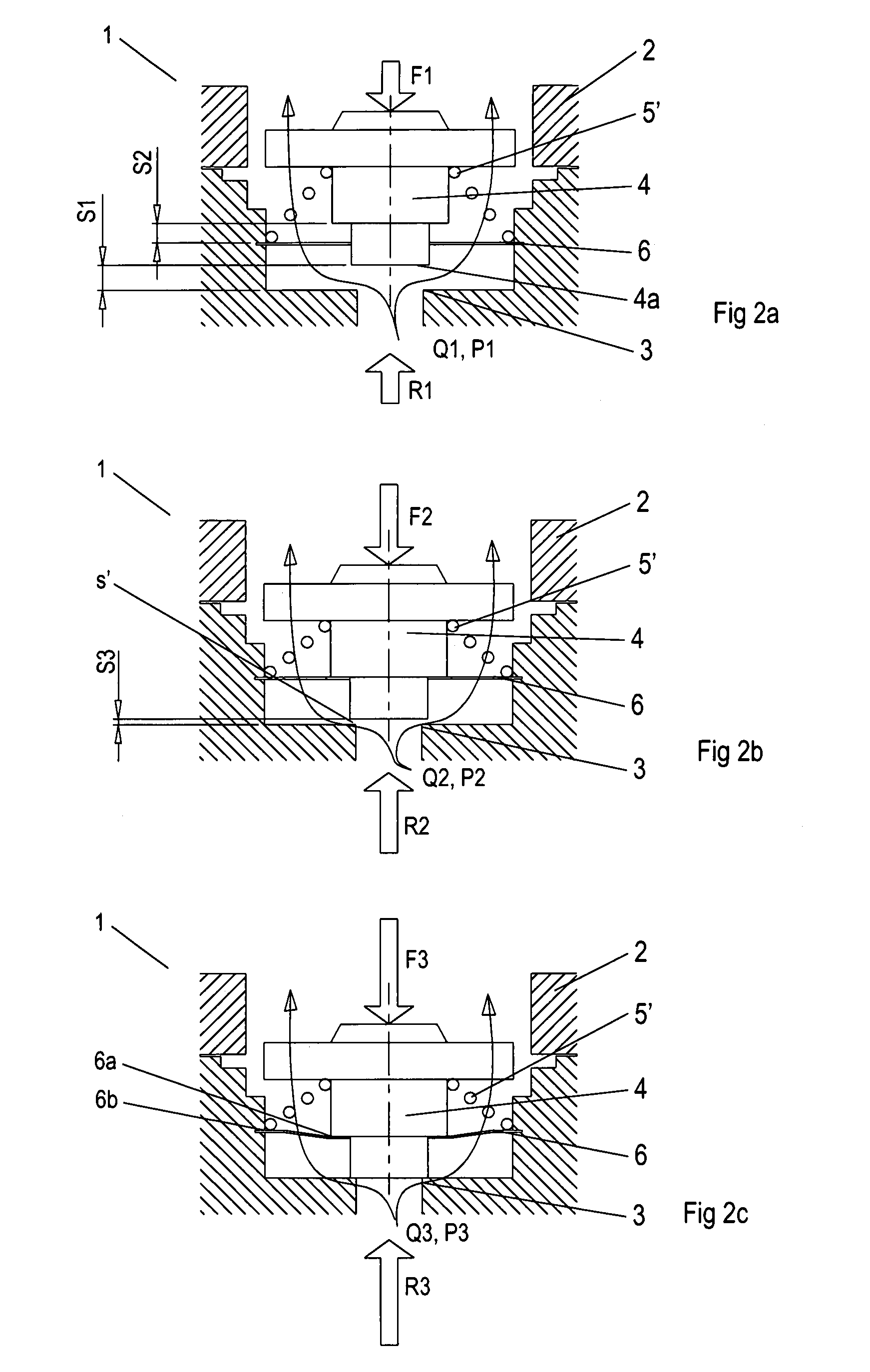
[0045]In FIGS. 2a-c, the invention is shown, in which one of the springs, preferably the first spring 5, instead has the form of a regular helical spring 5′. The first end 5a′ of the helical spring 5′ bears against the movable valve part 4 and the second end 5b′ rests on the fastening point of the second spring 6 in the valve housing 2. In this embodiment too, the helical spring 5′ acts counter to the actuating force F.

[0046]By using a flat and accurate washer-shaped spring as the second spring 6, as in FIGS. 2a-2c, an accurate distance, represented by S3, is attained. The accuracy of the distance S3, in the interaction between actuating force F and spring force, gives a regulator force R, which is independent of tolerances, and also a tolerance-independent minimum pressure level P. The strength of the washer-shaped spring is also that it can be made progressive and gives an increased spring constant the closer the seat 3 comes to the bottom face 4a of the movable valve part. In thi...


PUM


Abstract

The invention relates to a pressure regulator (1) in a shock absorber valve. The pressure regulator (1) comprises an axially movable first valve part (4) and a first seat (3), which are arranged in a valve housing (2) in such a way that an adjustable flow opening is created between the parts (3, 4). The flow opening is arranged to restrict a damping medium flow (q) and its flow opening size (s) is determined by a force balance on the first valve part (4). The force balance is principally or partially created by the sum of an actuating force (F) and the force (Fs) from a spring arrangement counter to the action of a counter holding regulator force (R). The spring arrangement comprises a first spring (5) having a first spring constant (k1) and a second spring (6) having a second spring constant (k2). The counter holding regulator force (R) is determined by the spring characters of both the first and the second spring (5, 6), in which the first spring (5) interacts with the actuating force (F) throughout the stroke (S1) and the second spring (6) works in series with the first spring (5) in an initial stroke (S3) close to the seat (3), in which the size of the initial stroke is determined by the working range of the second spring (6).

Description

TECHNICAL FIELD[0001]The invention relates to a pressure regulator comprising a spring arrangement intended to determine the pressure in a damping medium flow between the damping chambers of a shock absorber.BACKGROUND OF THE INVENTION[0002]Within shock absorber valve technology, a clear need has arisen to produce a pressure regulator having a bleeder-like character, which means that its opening pressure must as far as possible approach zero when the flow approaches zero. The pressure regulator must additionally have a low “blow off” or “cracking pressure” opening point, here referred to as the opening pressure, for all settings, modulations or spring biases, despite the fact that at higher pressures it must generate high pressures within the working range.[0003]A known embodiment of a pressure regulator having a bleeder-like character comprises a spring arrangement consisting of a first spring and a second spring, in which the first spring biases the second spring and contributes t...

Claims


Application Information

Patent Timeline
IPC IPC(8): F16F9/34
CPCF16F9/34F16F9/464Y10T137/7793F16F9/465F16F9/48F16F9/3207F16F9/348
Inventor SONSTEROD, LARSHOVEN, ARNOLD
Owner OHLINS
Why Eureka
Try Eureka