
Flange for Fuel Pump Module and Manufacturing Method Thereof

a fuel pump module and flange technology, which is applied in the direction of liquid fuel feeders, machines/engines, mechanical equipment, etc., can solve the problems of reducing the adhesion between the power supply terminal and the power supply terminal, reducing the adhesion force, and no longer maintaining air tightness, so as to prevent the probability of creating a gap, increase the adhesion force, and enhance the sealing performance

Active Publication Date: 2011-08-25
COAVIS
View PDF9 Cites 7 Cited by
  • Summary
  • Abstract
  • Description
  • Claims
  • Application Information

AI Technical Summary

Benefits of technology

Accordingly, the present invention has been made keeping in mind the problems encountered in the related art and the present invention is intended to provide a flange for a fuel pump module and a method of manufacturing the same, in which an adhesion enhancing member may be simply formed on a power supply terminal using a thermosetting adhesive tape, thus increasing the force of adhesion between the power supply terminal and a resin material for forming a flange and preventing the probability of creating a gap between them to thereby enhance sealing performance.
In particular, the present invention is intended to provide a flange for a fuel pump module and a method of manufacturing the same, in which fuel or gas may be prevented from leaking from a fuel tank, thus meeting strict exhaust gas regulations.
In this aspect, the adhesion enhancing member may comprise a thermosetting material, and the method may further comprise heat-hardening the adhesion enhancing member so as to increase bondability between the adhesion enhancing member and the power supply terminal, after forming the adhesion enhancing member.

Problems solved by technology

However, the resin having high heat resistance also has a high melting point, making it difficult to perform an injection process, and also upon cooling, drastic changes in temperature may decrease the adhesion between the power supply terminal and the resin, undesirably creating a gap between them.
In cases where the gap is created between the power supply terminal and the resin material, the fuel or gas may be discharged from the fuel tank via the gap and thus airtightness is no longer maintained.
Also, it is difficult to simply check with the naked eye whether such a gap is created, undesirably causing a deterioration in production efficiency.

Method used


Image

  • Flange for Fuel Pump Module and Manufacturing Method Thereof
  • Flange for Fuel Pump Module and Manufacturing Method Thereof
  • Flange for Fuel Pump Module and Manufacturing Method Thereof

Examples


Embodiment Construction

Hereinafter, a detailed description will be given of a flange 100 for a fuel pump module and a method of manufacturing the same according to the present invention with reference to the appended drawings.

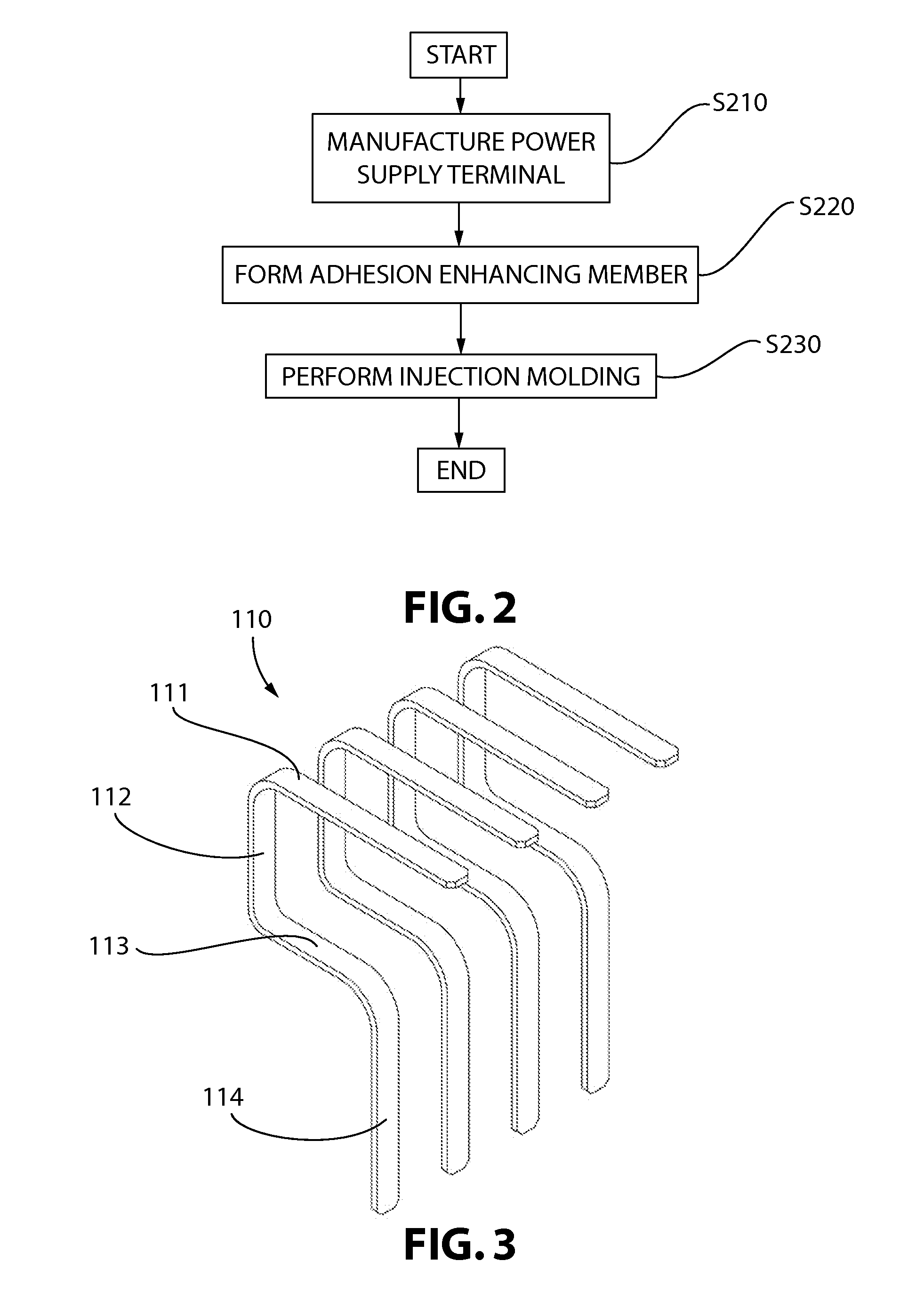
According to the present invention, the method of manufacturing the flange 100 for a fuel pump module, which is integratedly injected with a power supply terminal 110 and is affixed to a fuel tank, includes manufacturing the power supply terminal 110 (S210), forming an adhesion enhancing member 120 (S220), and performing injection molding (S230).

In manufacturing the power supply terminal 110 (S210), the power supply terminal is manufactured using a metal having high conductivity or metal alloy.

The power supply terminal 110 may be variously formed. As illustrated in FIG. 3, the power supply terminal 110 may include a first terminal portion 111 extending in a horizontal direction at one side thereof, a first bent portion 112 that is downwardly bent at one side of the first terminal por...


PUM

PropertyMeasurementUnit
melting pointaaaaaaaaaa
temperatureaaaaaaaaaa

Abstract

Disclosed is a flange for a fuel pump module, which includes an adhesion enhancing member so that there is no gap between a power supply terminal and a resin material for forming a flange, thus further increasing injection efficiency and sealing performance. A method of manufacturing such a flange is also provided.

Description

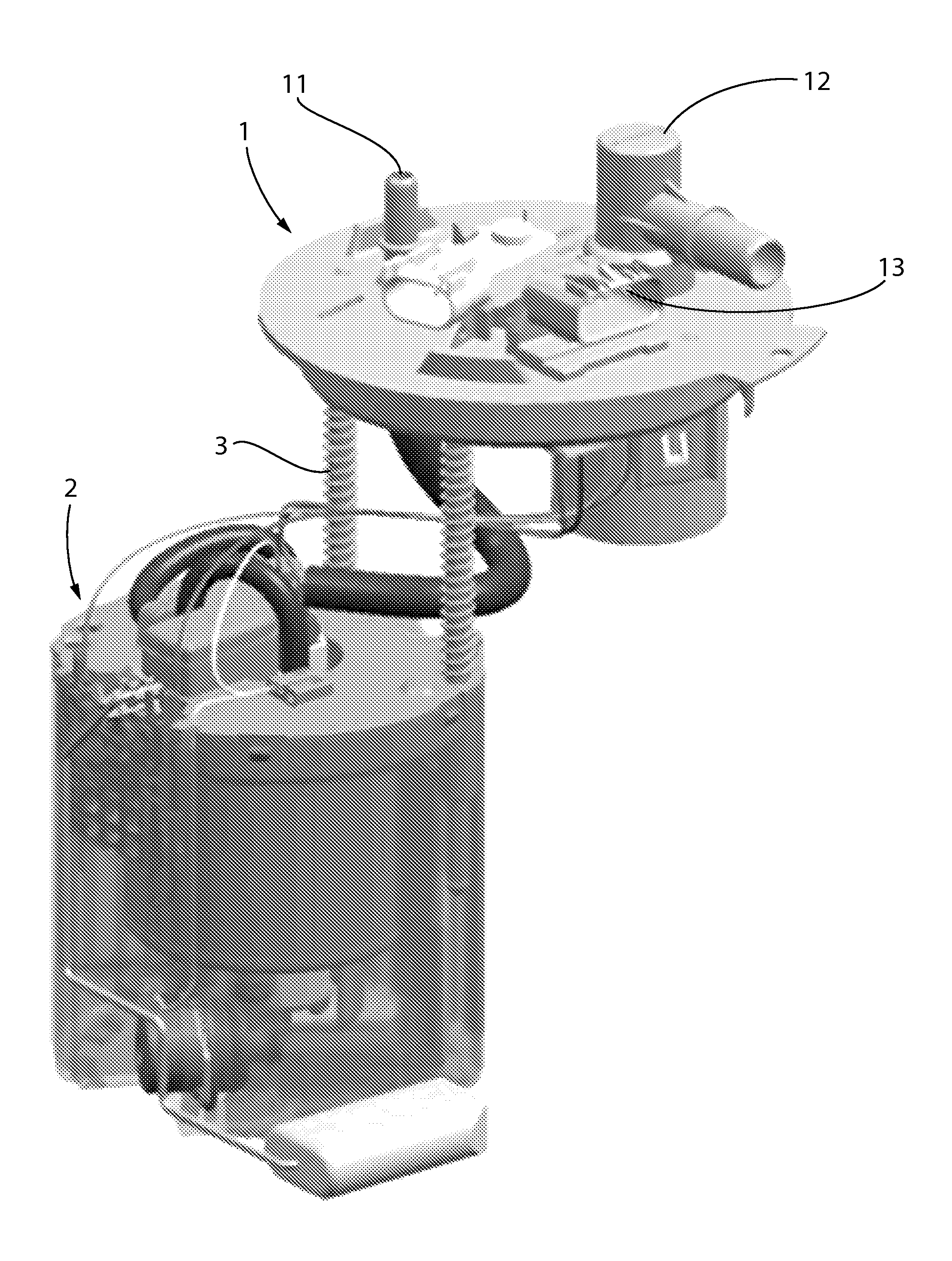
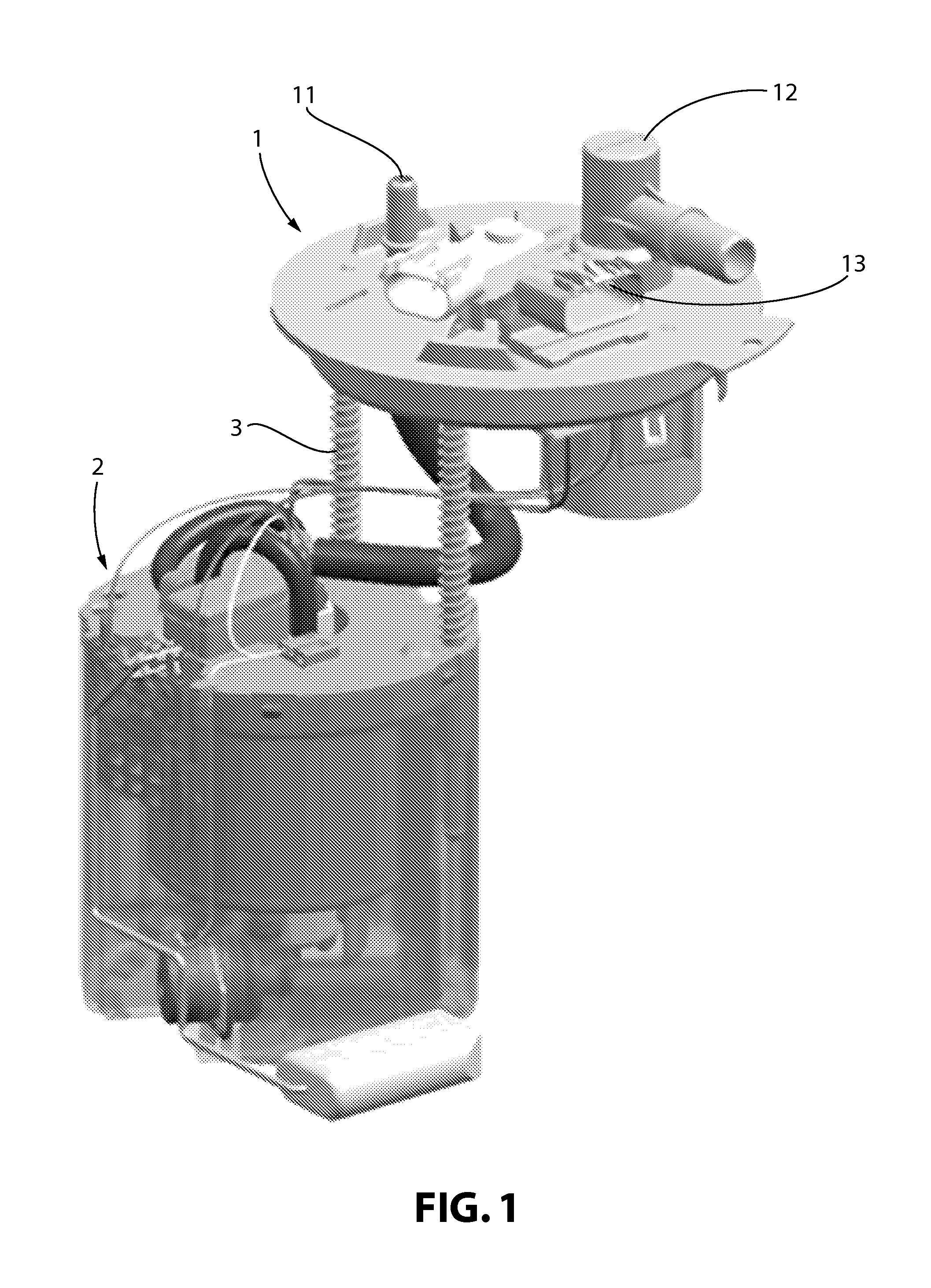
BACKGROUND OF THE INVENTION1. Field of the InventionThe present invention relates to a flange for a fuel pump module and a method of manufacturing the same, and more particularly, the present invention relates to a flange for a fuel pump module, which includes an adhesion enhancing member so that there is no gap between a power supply terminal and a flange forming resin material, thus further increasing injection efficiency and sealing performance, and to a method of manufacturing the same.2. Description of the Related ArtTypically, devices such as gasoline or diesel engines which receive liquid fuel to operate vehicles and so on include a fuel tank for storing fuel, and a fuel pump module provided in the fuel tank so that fuel stored in the fuel tank is forcibly fed to the engine.The fuel pump module is shown in FIG. 1.The fuel pump module includes a flange assembly 1 affixed to a fuel tank, and a reservoir body assembly 2 connected to the lower surface of the flange assembly 1 by ...

Claims


Application Information

Patent Timeline
Patent Type & Authority Applications(United States)
IPC IPC(8): F16L23/00B29C45/14
CPCY10T156/10F02M2037/228F02M37/106Y10T29/49236Y10T29/49206Y10T29/49982F02M37/103F02M37/50
Inventor CHO, HA YOUNGCHOI, JAE WONKIM, JIN SEOK
Owner COAVIS
Learn More