System and method for communicating with a telemetric implant

Active Publication Date: 2011-08-25
SMITH & NEPHEW INC
View PDF106 Cites 44 Cited by
  • Summary
  • Abstract
  • Description
  • Claims
  • Application Information

AI Technical Summary

Benefits of technology

[0013]It is in view of the above problems that the present invention was developed. According to some aspects of the present invention, there may be provided a telemetric system. The telemetric system includes a telemetric implant, a reader unit adapted to read signals from the telemetric implant; and an antenna

Problems solved by technology

However, skepticism of the risks associated with wireless power and communication systems has prevented widespread adoption, particularly in orthopaedic applications.
Today's medical de

Method used


Image

  • System and method for communicating with a telemetric implant
  • System and method for communicating with a telemetric implant
  • System and method for communicating with a telemetric implant

Examples


first embodiment

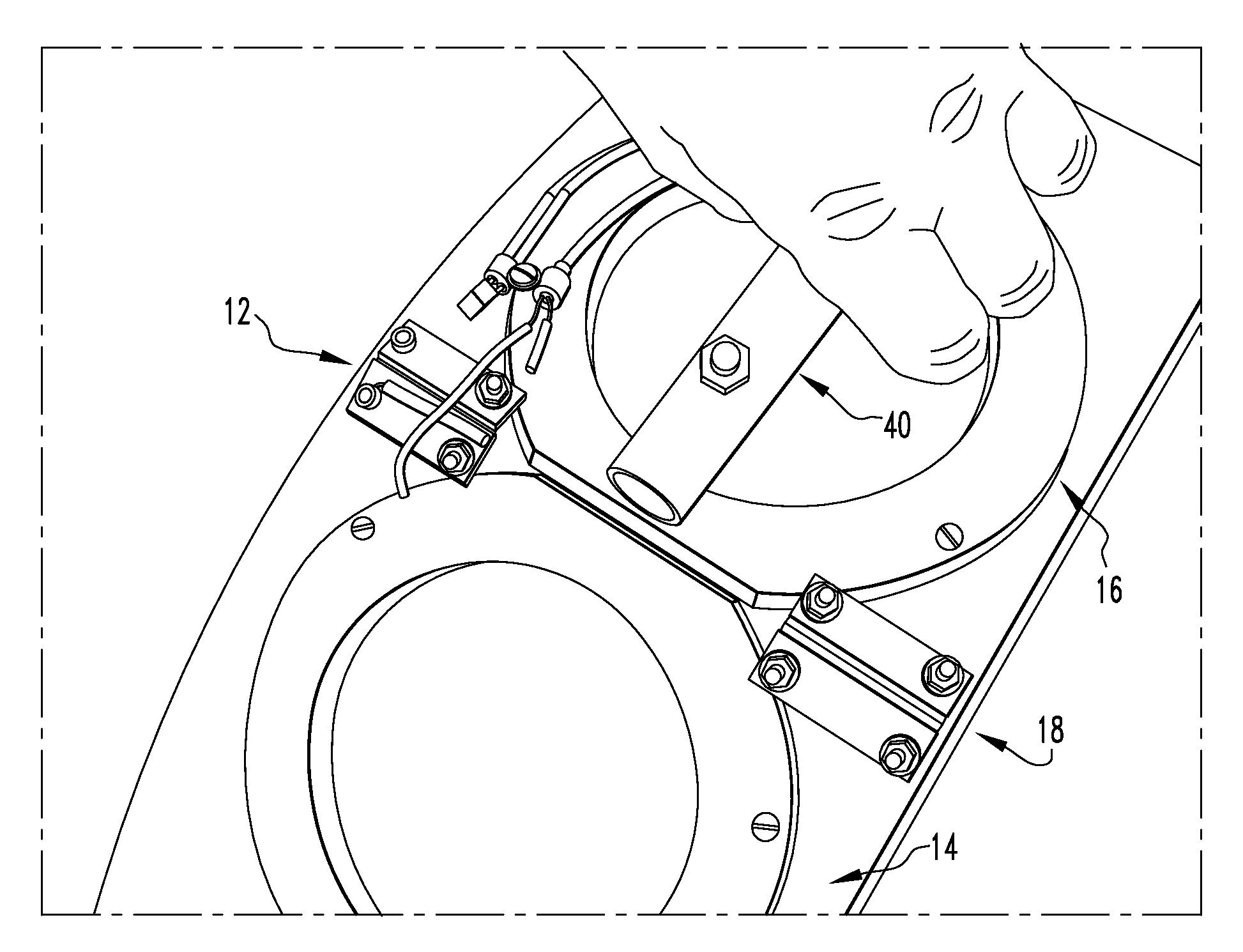
[0051]FIG. 4 illustrates the antenna 12. The coils 14, 16 are housed in a flexible polymer and are joined together in the middle using the hinge 18. The antenna 12 is equipped with a handle 40 that allows the device to be held by the user.

second embodiment

[0052]FIGS. 5A and 5B illustrate the antenna 12. The coils 14, 16 are housed in a pouch 50 attached to a belt 52 that is worn around the patient's waist. The pouch 50 and the belt 52 give the patient more mobility during powering and data logging from the implant 500.

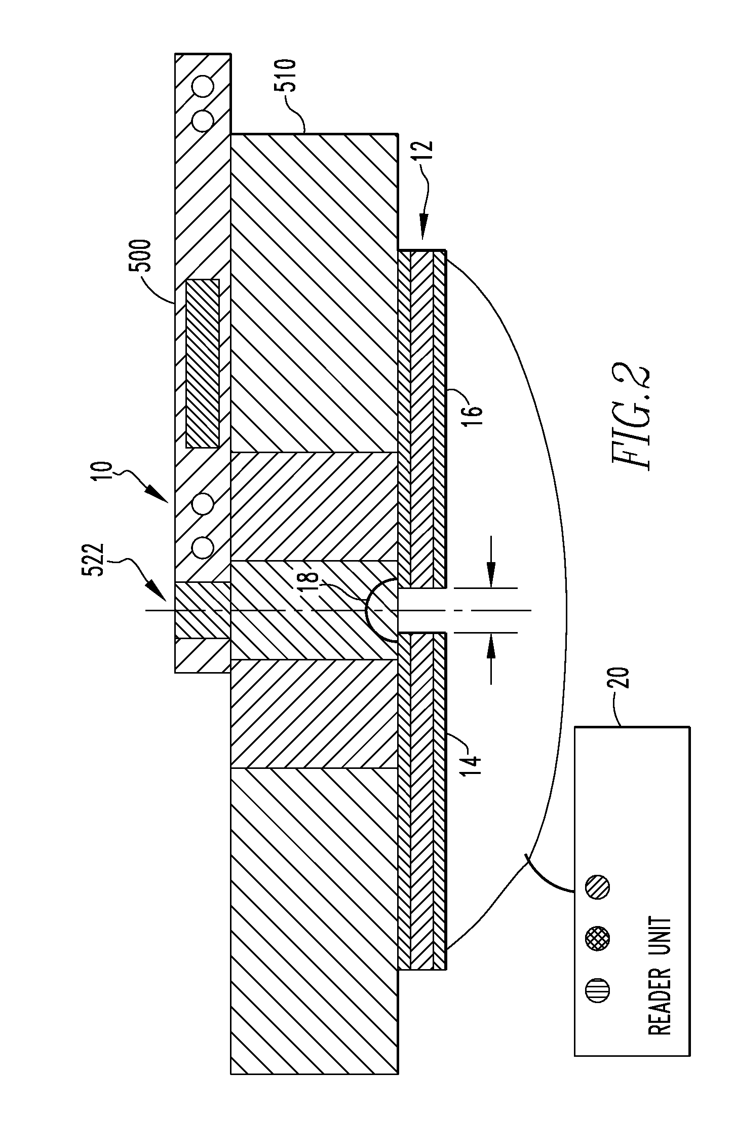
[0053]FIG. 6 illustrates a block diagram of the telemetric system 10. The system architecture includes a hand-held dual coil antenna 12, a reader unit 20, a computing device 60, a signal generator 70, and a power supply 80. Optionally, the system 10 may include an audible feedback system that informs the user when the implant is engaged and reliable data is being acquired. The antenna 12, which also may be termed a reader head, may be equipped with one or more signal “OK” light emitting diodes (LEDs) 24 to provide feedback to the user on optimizing the position of the reader relative to the implant 500. In an exemplary case, the signal “OK” LED 24 is illuminated when the implant frequency is between 5.3 kHz and 6.3 kHz ...


PUM


Abstract

A telemetric system (10, 300) is disclosed. The telemetric system (10, 300) includes a telemetric implant (400, 500), a reader unit (20) adapted to read signals from the telemetric implant (400, 500), and an antenna (12, 212, 312) adapted for connection to the reader unit (20, 320) and to receive signals from the telemetric implant (400, 500). The antenna (12, 212, 312) has a first coil (14, 214, 314), a second coil (16, 216, 316), and a connector (18, 318). The first coil (14, 214, 314) is electrically connected to the second coil (16, 216, 316), and the connector (18, 318) allows for movement of the first and second coils (14, 214, 314, 16, 216, 316) relative to each other. The antenna (12, 212, 312) may be used to send radio-frequency power to the telemetric implant (400, 500) and receives data from the telemetric implant (400, 500).

Description

CROSS-REFERENCE TO RELATED APPLICATIONS[0001]This application claims priority to U.S. Provisional Patent Application No. 60 / 970,460, filed on 6 Sep. 2007. This prior application is incorporated by reference herein.BACKGROUND OF THE INVENTION[0002]1. Field of the Invention[0003]The present invention relates generally to telemetric systems and more particularly to devices for adjusting the electromagnetic field of a telemetric system.[0004]2. Related Art[0005]Wireless technology in devices such as pagers and hand-held instruments has long been exploited by the healthcare sector. However, skepticism of the risks associated with wireless power and communication systems has prevented widespread adoption, particularly in orthopaedic applications. Now, significant advances in microelectronics and performance have eroded many of these perceived risks to the point that wireless technology is a proven contender for high integrity medical systems. Today's medical devices face an increasingly d...

Claims


Application Information

Patent Timeline
IPC IPC(8): G08C19/00
CPCA61F2250/0002A61M2205/3523H01Q7/02A61N1/37229H01Q1/2216A61M2205/3592A61N1/375H01Q7/00
Inventor JANNA, SIED W.WILSON, DARREN J.GOODCHILD, MARTIN S.BRADY, PETER A.
Owner SMITH & NEPHEW INC
Why Eureka
Try Eureka