Demand response method, computer-readable medium and system

Active Publication Date: 2011-08-25
SAMSUNG ELECTRONICS CO LTD
View PDF12 Cites 58 Cited by
  • Summary
  • Abstract
  • Description
  • Claims
  • Application Information

AI Technical Summary

Benefits of technology

[0010]Therefore, it is an aspect of the example embodiments to provide a demand response method, computer-readable medium and system that reduce p

Problems solved by technology

That is, the conventional DR system has been designed to limit the operation of household appliances in response to power rates, which may

Method used


Image

  • Demand response method, computer-readable medium and system
  • Demand response method, computer-readable medium and system
  • Demand response method, computer-readable medium and system

Examples


Example

[0043]Reference will now be made in detail to the embodiments, examples of which are illustrated in the accompanying drawings, wherein like reference numerals refer to like elements throughout.

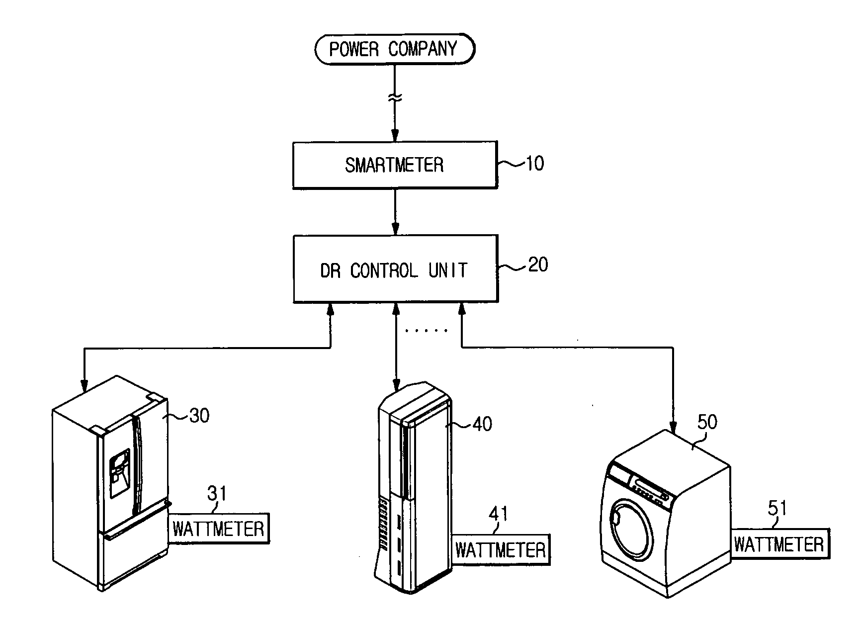
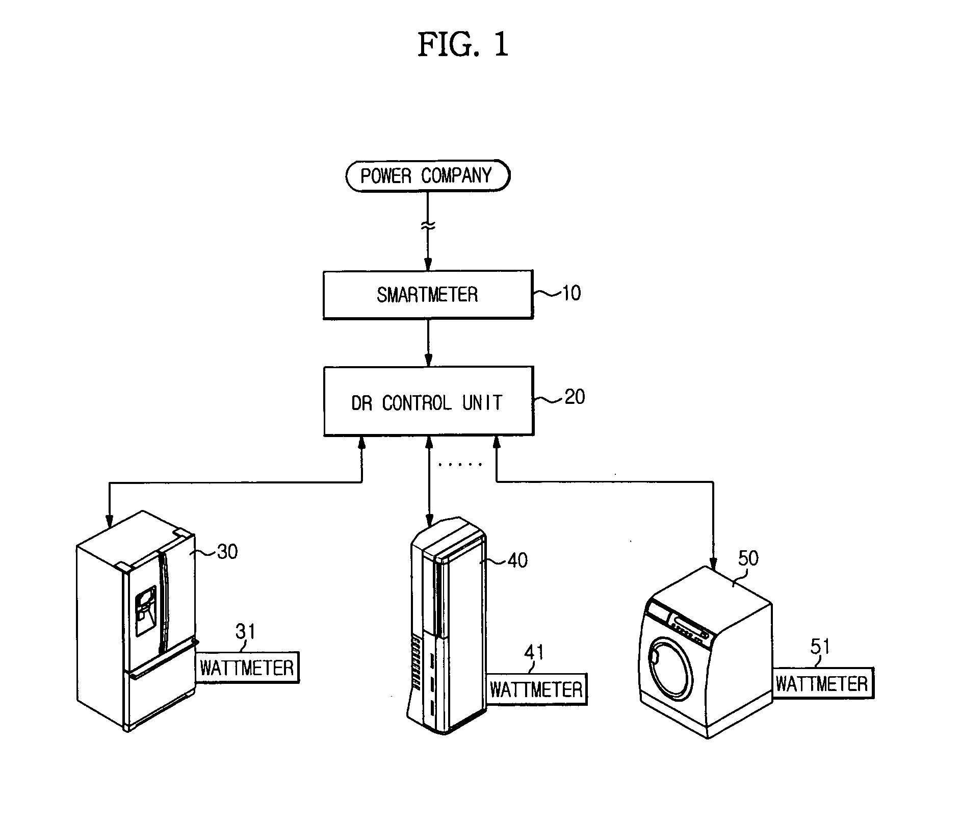
[0044]FIG. 1 is a configuration diagram illustrating a demand response (DR) system according to example embodiments.

[0045]Referring to FIG. 1, the DR system may include a smartmeter 10 installed in a home to transmit and receive information to and from a power company; a DR control unit 20 to receive information about electric demand or electric charges from the smartmeter 10; and respective household appliances 30, 40 and 50 connected to the DR control unit 20 over a network.

[0046]Each household appliance 30, 40 or 50 may perform a desired function using power received through a power line.

[0047]The amount of power consumed by each household appliance 30, 40 or 50 may be measured by a wattmeter 31, 41 or 51 installed in the household appliance 30, 40 or 50. Each wattmeter 31, 41 or 51 may mea...


PUM


Abstract

A demand response (DR) system, computer-readable medium and method are disclosed. The DR system controls a high-power-consumption load to be pre-operated or post-operated in a low-power-rate interval instead of a high-power-rate interval, and reduces an amount of power consumption required for a high-power-rate interval, resulting in reduction of power rates. In addition, limitation to household appliance operation is minimized, to greatly reduce inconvenience of a user.

Description

CROSS-REFERENCE TO RELATED APPLICATIONS[0001]This application claims the benefit of Korean Patent Application No. 10-2010-0015403, filed on Feb. 19, 2010 in the Korean Intellectual Property Office, the disclosure of which is incorporated herein by reference.BACKGROUND[0002]1. Field[0003]Example embodiments relate to a demand response method, a computer-readable medium and system reducing peak power rates when power rates are high to reduce electricity bills.[0004]2. Description of the Related Art[0005]Generally, it is necessary for a power system to balance demand and supply. This requirement of the power system is of importance to rational utilization of limited energy resources.[0006]For the aforementioned purposes, demand management is a focus of attention, and a number of studies are underway into demand response (DR) about the developed demand management formats.[0007]The demand response (DR) can be defined as a variation of consumption format depending on variation in power ra...

Claims


Application Information

Patent Timeline
IPC IPC(8): G06F1/26
CPCY04S20/242Y04S20/224Y02B70/3266Y04S20/222H02J3/14Y02B70/3225H02J2310/14Y02B70/30G06Q50/06H02J3/144
Inventor YANG, JANG BEOMPARK, JUNG WONJEONG, SEONG WOOKLEE, CHANG HERNGIM, SEONG CHANJANG, YOUNG HOLIM, JAE MINCHO, SUNG HOJIN, SUN ILSON, CHANG HOBAEK, YOUNG JIN
Owner SAMSUNG ELECTRONICS CO LTD
Why Eureka
Try Eureka