Method of setting performance characteristic of pump and method of manufacturing diffuser vane

Active Publication Date: 2011-09-01
MITSUBISHI HEAVY IND LTD
View PDF17 Cites 4 Cited by
  • Summary
  • Abstract
  • Description
  • Claims
  • Application Information

AI Technical Summary

Benefits of technology

[0010]According to a method of setting a performance characteristic of a pump of claim 1, it is possible to easily set a performance characteristic of a pump by setting a mounting position of a diffuser vane to an arbitrary mounting position according to performance of the pump in a perpendicular direction. More specifically, if the mounting position of the diffuser vane in the perpendicular direction is set, an inlet angle of the diffuser vane is set according to the former setting. If the inlet angle of the diffuser vane is set, the performance characteristic of the pump is set. At this time, a bending curvature of the diffuser vane is not changed. Therefore, deterioration in the performance of the pump that is caused by a shape change of the diffuser vane can be suppressed. With this configuration, it is unnecessary to newly design the diffuser vane according to the setting of the performance characteristic of the pump, and it is possible to set the performance charact

Problems solved by technology

However, because the bending curvature of the diffuser vane is largely changed, the optimal shape the

Method used


Image

  • Method of setting performance characteristic of pump and method of manufacturing diffuser vane
  • Method of setting performance characteristic of pump and method of manufacturing diffuser vane
  • Method of setting performance characteristic of pump and method of manufacturing diffuser vane

Examples


embodiments

[0044]A pump according to an embodiment of the present invention is a so-called vertical diffuser mixed-flow pump (hereinafter, “mixed-flow pump”), and the mixed-flow pump sends out, toward a discharge port, fluid (such as city water) sucked from a suction port by rotating an impeller.

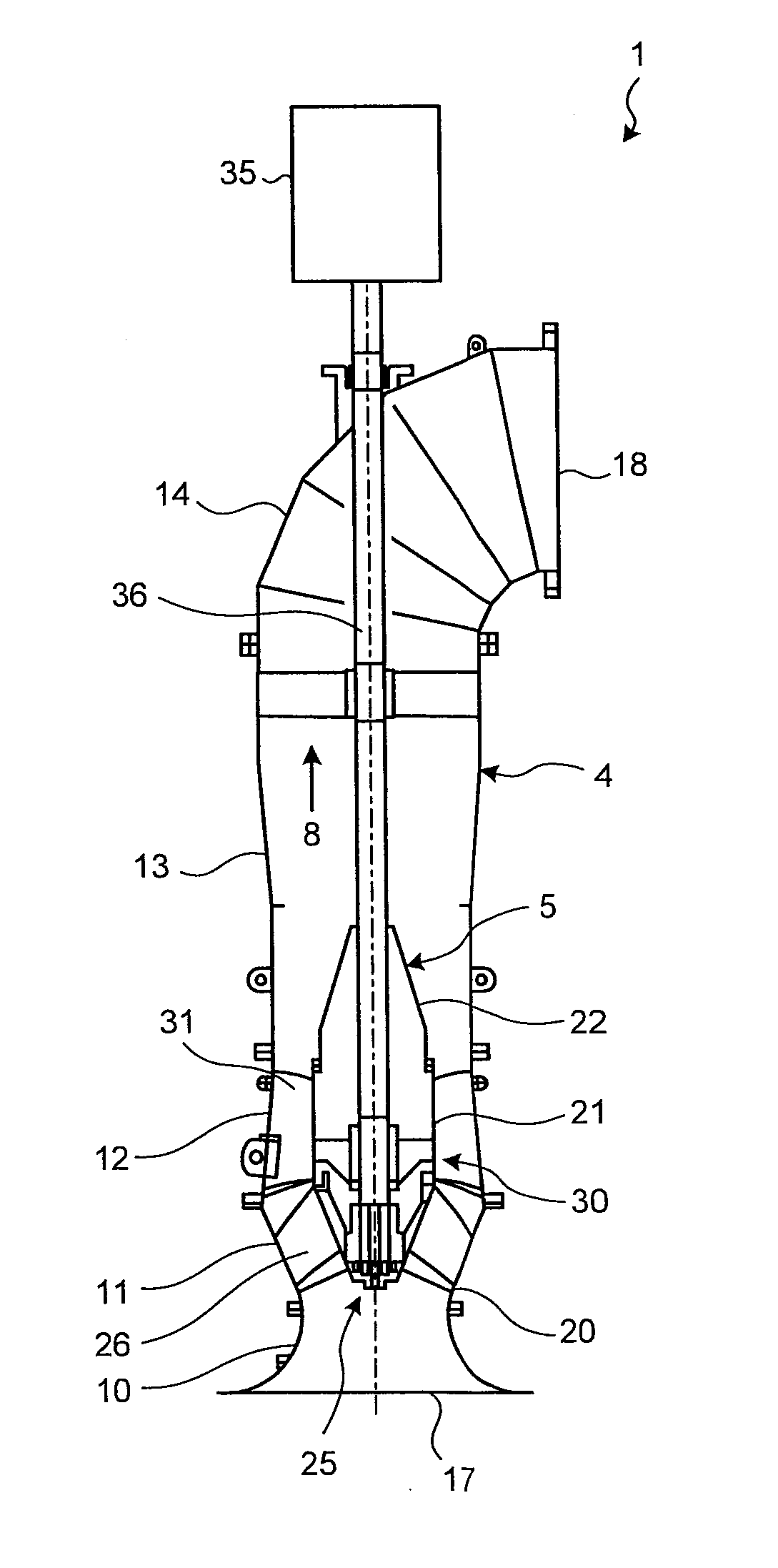
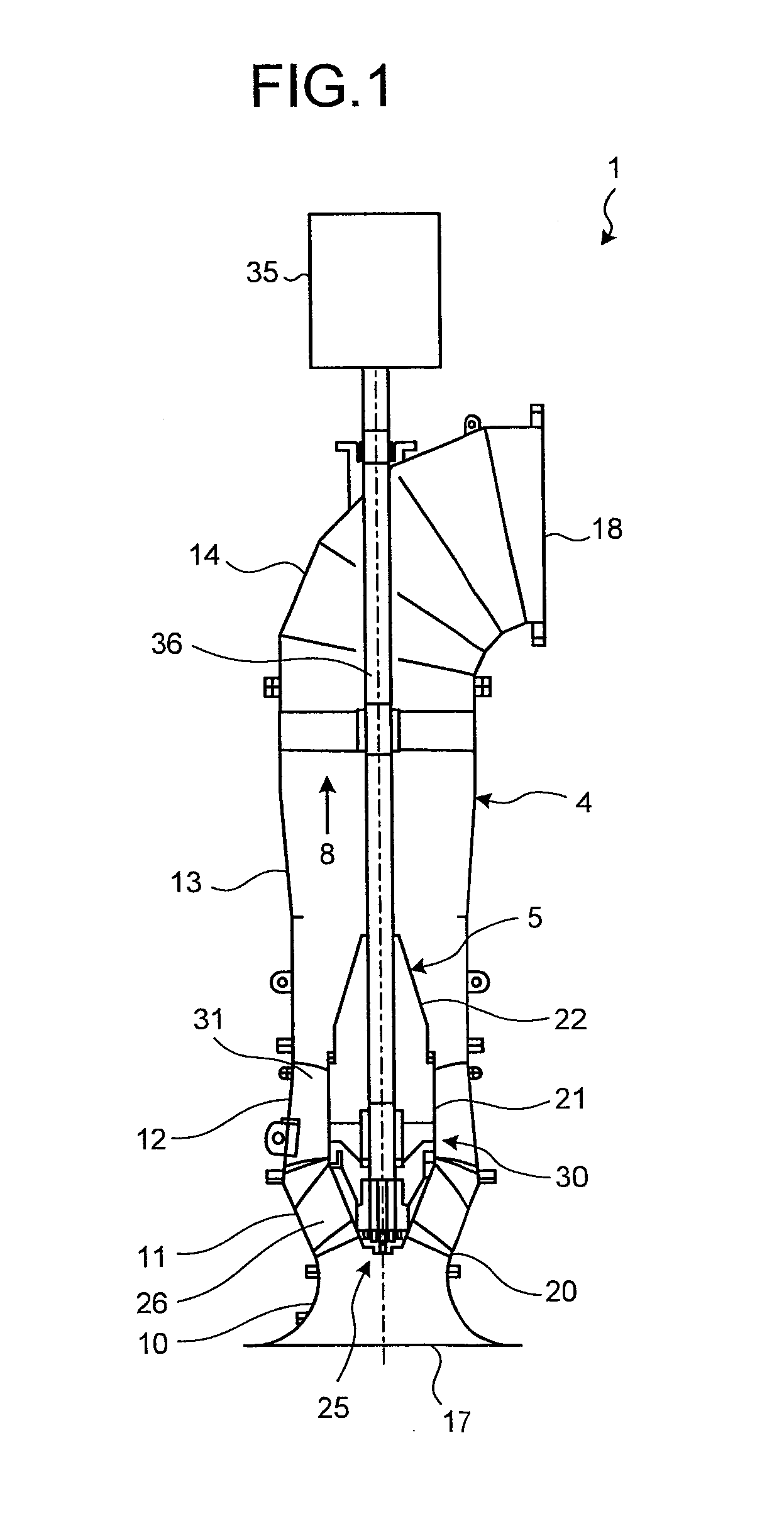
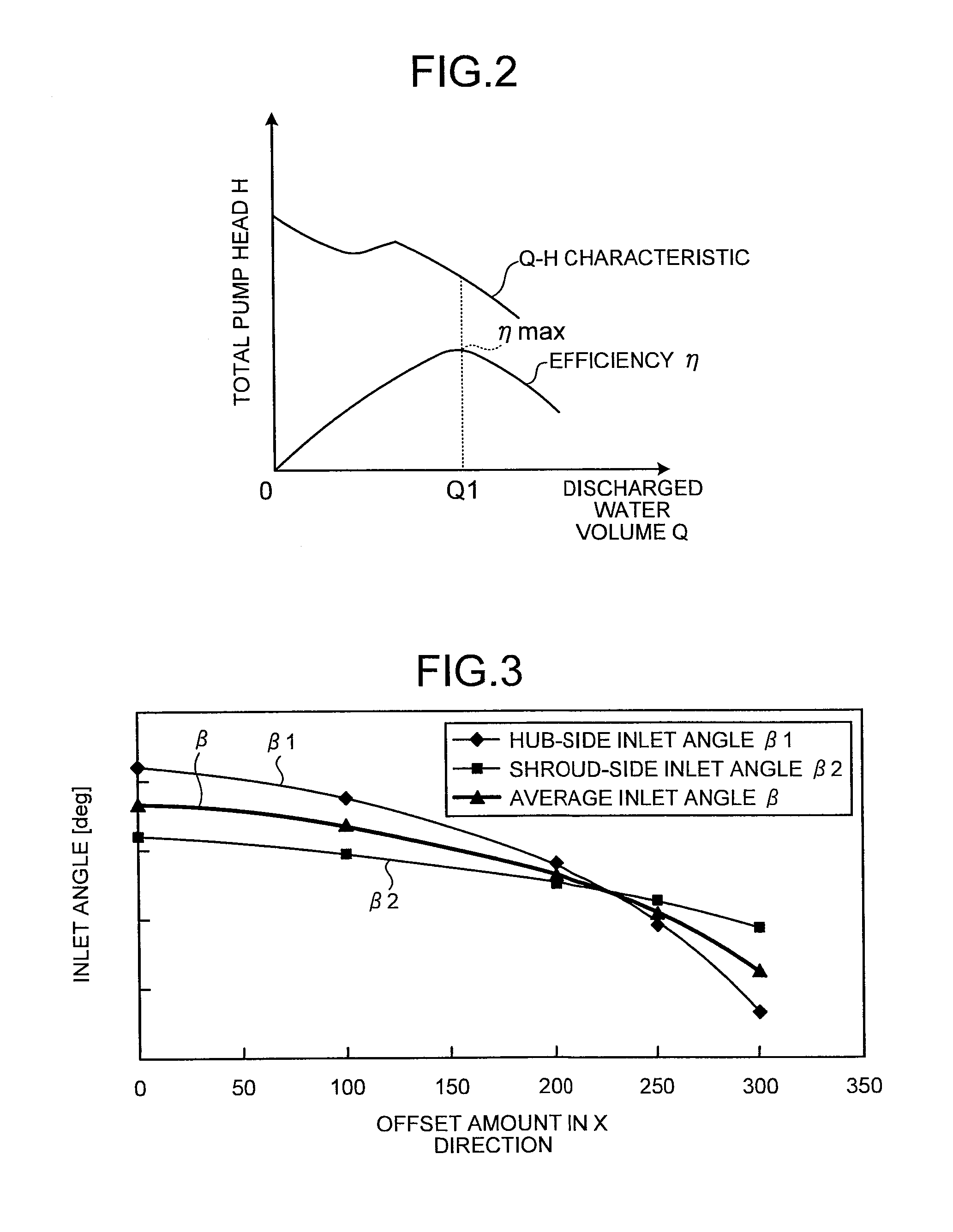
[0045]FIG. 1 is a cross-sectional configuration diagram of the mixed-flow pump according to the present embodiment, and FIG. 2 depicts a Q-H characteristic curve of the mixed-flow pump. FIG. 3 is a graph of a changing rate of an offset amount that is changed according to a set average inlet angle, and FIG. 4 is an explanatory diagram of mounting positions of diffuser vanes. FIG. 5 is a cutting plan view of the diffuser vanes, and FIG. 6 is an explanatory diagram of a sheet metal member that is bent at a bending step. A configuration of the mixed-flow pump is described below with reference to FIG. 1.

[0046]As shown in FIG. 1, a mixed-flow pump 1 includes an outer cylinder casing 4 constituting a hull of ...


PUM


Abstract

To provide a method of setting a performance characteristic of a pump for setting a performance characteristic of a pump, the pump including an impeller that takes in fluid from a suction port and that sends out the fluid toward a discharge port, and a diffuser provided in a flow passage between the impeller and the discharge port, where the diffuser includes a hub arranged in a central portion of the flow passage, a shroud arranged around a periphery of the hub, and a plurality of diffuser vanes radially arranged from an outer peripheral surface of the hub toward an inner peripheral surface of the shroud, and the method includes a mounting-position setting step of setting a mounting position of each of the diffuser vanes to be mounted on the hub according to the performance characteristic of the pump in a direction perpendicular to a radial direction extending from the hub toward the shroud.

Description

TECHNICAL FIELD[0001]The present invention relates to a method of setting a performance characteristic of a pump for setting a performance characteristic of a pump having a diffuser, and relates to a method of manufacturing a diffuser vane.BACKGROUND ART[0002]A mixed-flow pump and an axial-flow pump have been known as conventional pumps. Each of the mixed-flow pump and the axial-flow pump includes an impeller that sends out fluid in a rotation-axial direction, and a diffuser provided downstream of the impeller (see, for example, Patent Document 1).[0003]As the mixed-flow pump, a type of pump having an appropriate performance characteristic suitable for an installation environment is used so that the mixed-flow pump can be efficiently operated according to its installing location or the use for the pump. In this case, if an inlet angle of each of diffuser vanes provided in the diffuser is set to a desired inlet angle, the performance characteristic of the mixed-flow pump can be set t...

Claims


Application Information

Patent Timeline
IPC IPC(8): B23P15/00
CPCY10T29/49243F04D15/0088F04D13/08F04D29/448F04D3/00F04D29/548Y10T29/49245Y10T29/49236F04D29/628
Inventor KOBAYASHI, KAZUTA
Owner MITSUBISHI HEAVY IND LTD
Why Eureka
Try Eureka