Fuel tank

a fuel tank and tank body technology, applied in the field of fuel tanks, can solve the problems of increasing the scale of the fuel tank, increasing the cost, and deteriorating the start-up performance of the engine, so as to reduce the excess fuel transfer, simple structure, and reliable start

Inactive Publication Date: 2011-09-01
HONDA MOTOR CO LTD
View PDF6 Cites 19 Cited by
  • Summary
  • Abstract
  • Description
  • Claims
  • Application Information

AI Technical Summary

Benefits of technology

[0009]The present invention is made to resolve this type of problem. An object of the invention is to provide a fuel tank which suppresses excess transfer of fuel in an amount more than needed between a first reservoir portion and a second reservoir portion, at times when the vehicle is being driven around a curve, or when the vehicle is parked on an incline, and which enables the engine to reliably be started by means of a simple structure.

Problems solved by technology

For this reason, compared to a 2WD (two wheel drive) vehicle, two respective fuel pumping systems are required, which leads to a rise in cost and increases the scale of the fuel tank.
As a result, fuel cannot be supplied through the pump module 3, and the start-up performance of the engine is deteriorated.

Method used


Image

  • Fuel tank
  • Fuel tank
  • Fuel tank

Examples


Embodiment Construction

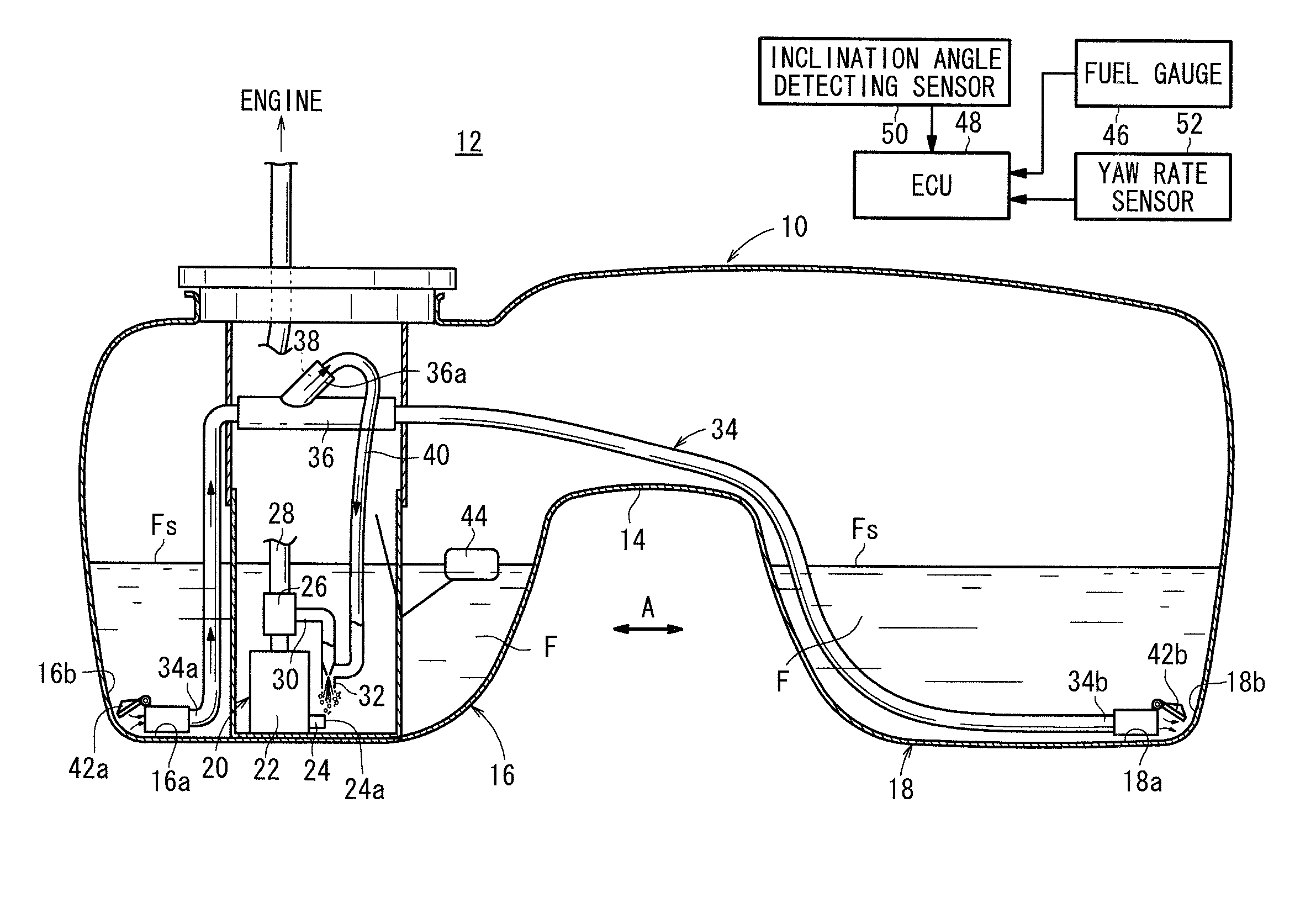
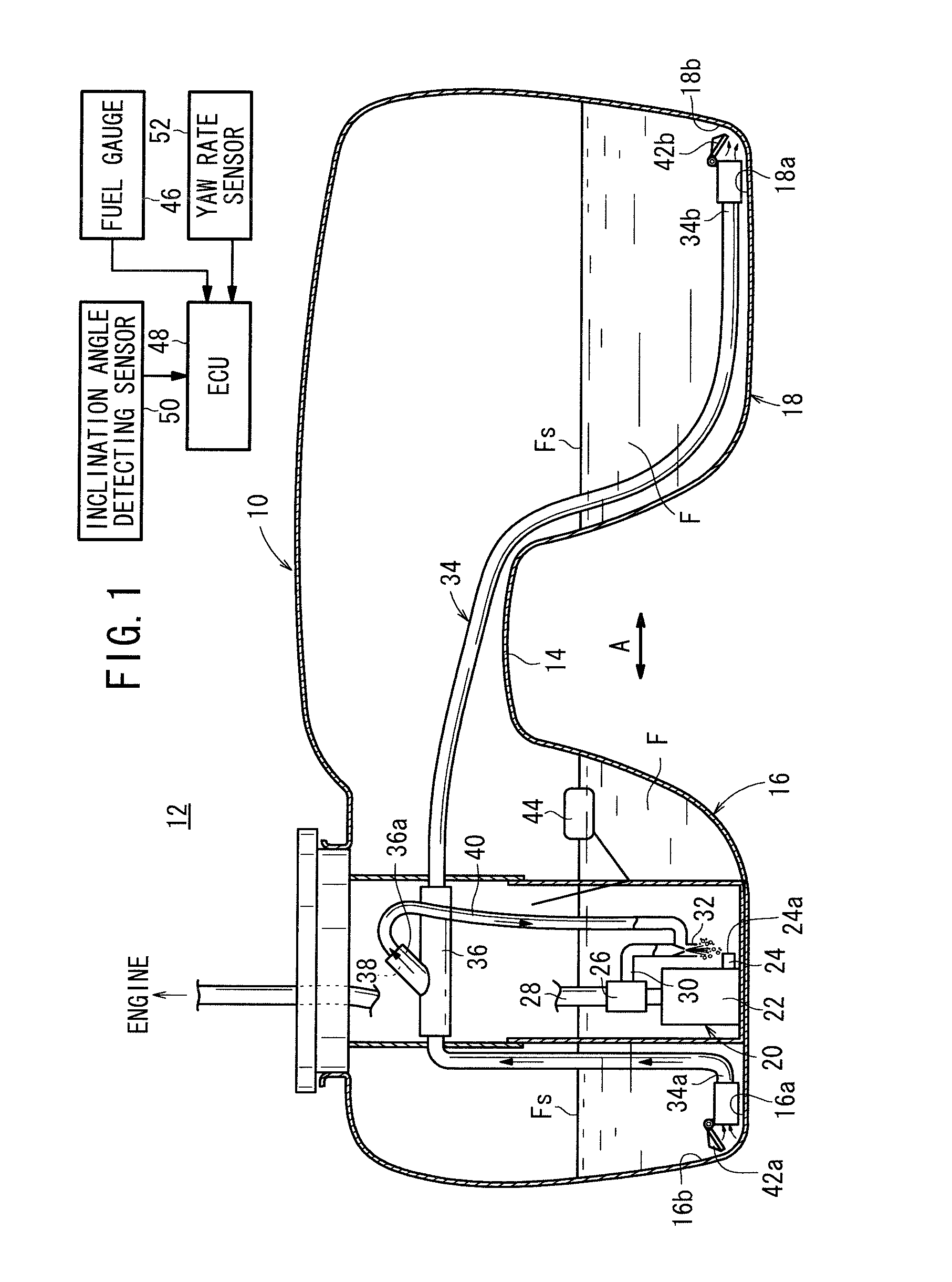
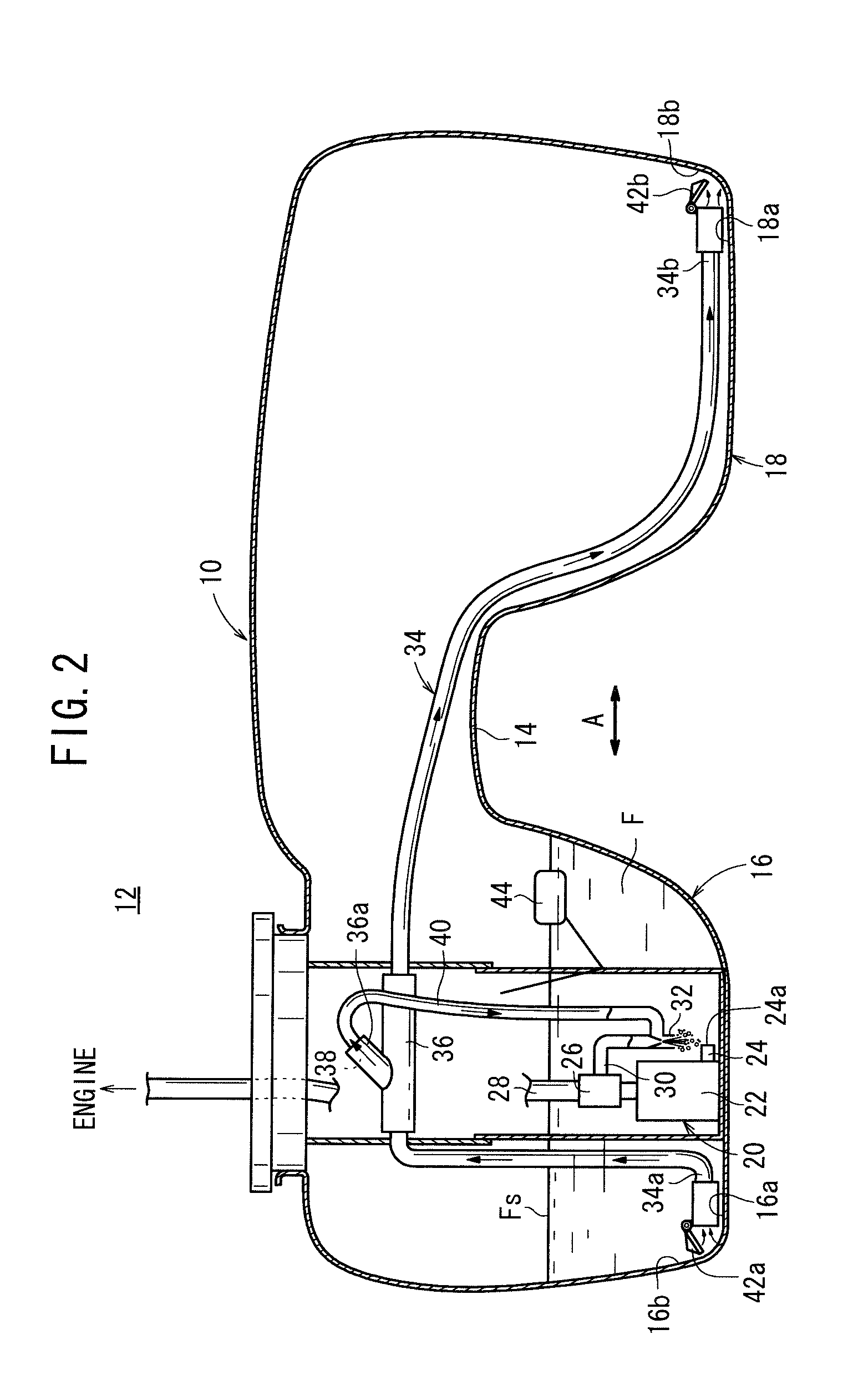
[0019]As shown in FIG. 1, a fuel tank 10 according to an embodiment of the present invention is incorporated into a fuel supply system 12. The fuel tank 10 is constructed as a saddle-type fuel tank, and is mounted onto a non-illustrated vehicle. An upwardly curved saddle portion 14 is disposed in a substantially central bottom part in the vehicle widthwise direction (the direction of the arrow A) of the fuel tank 10. A main tank portion (first reservoir portion) 16 and a sub-tank portion (second reservoir portion) 18 are formed by the saddle portion 14.

[0020]A fuel pump module 20 is disposed in the main tank portion 16. A fuel pump 22 constituting part of the fuel pump module 20 is equipped with a pumping jet pump 24, having a fuel suction inlet 24a that opens at a bottom part 16a of the main tank portion 16, whereas a pressure regulator 26 is connected on an outlet side of the fuel pump 22.

[0021]The pressure regulator 26 supplies fuel F to a non-illustrated engine via a fuel pipeli...


PUM


Abstract

A fuel tank is provided with: a fuel pump; a main tank section which has the fuel pump arranged therein and stores a fuel; a sub-tank section wherein the fuel is stored; and a siphon tube which is arranged over the main tank section and the sub-tank section, and sucks the fuel by means of the fuel pump. The open end of the siphon tube on the main tank section side is arranged outside a jet pump for suction.

Description

TECHNICAL FIELD[0001]The present invention relates to a fuel tank equipped with a fuel pump, a first reservoir portion in which the fuel pump is arranged and in which a fuel is retained, a second reservoir portion in which the fuel is retained, and a siphon tube disposed across the first reservoir portion and the second reservoir portion, suction being carried out in the siphon tube via the fuel pump.BACKGROUND ART[0002]A fuel tank is used for supplying fuel to an internal combustion engine. For example, in a 4WD (four wheel drive) vehicle or a FR (front engine, rear drive) vehicle, in order to avoid the propeller shaft that passes through the center of the vehicle, a so-called saddle type fuel tank, in which the center of a bottom part of the fuel tank in the widthwise direction of the vehicle is recessed upwardly, has been adopted.[0003]Generally, a saddle type fuel tank is divided into a first reservoir portion that retains fuel, and a second reservoir portion that also retains f...

Claims


Application Information

Patent Timeline
Patent Type & Authority Applications(United States)
IPC IPC(8): B60P3/00
CPCB60K15/03B60K2015/03118F02M37/106F02M37/0094F02M37/025B60K2015/03138Y10T137/6855
Inventor MURABAYASHI, SHINYANAKAJIMA, TAKEAKI
Owner HONDA MOTOR CO LTD
Why Eureka
Try Eureka