Error Compensating Method for Instrument Transformer

Inactive Publication Date: 2011-09-01
HANKOOK IED +1
View PDF8 Cites 2 Cited by
  • Summary
  • Abstract
  • Description
  • Claims
  • Application Information

AI Technical Summary

Benefits of technology

[0019]An advantage of the present invention is that it provides an error compensating method for an instrument transformer. In the error compensating method, hysteresis characteristics of iron core are used for compensating an error. In this case, a hysteresis loop indicating the relationship between magnetic flux and excitation current is not used as it is, but core-loss resistances and magnetic flux-excitation current curves are used. Therefore, interpolation is easily and precisely performed, so that precise compensation can be performed at a current, which is much smaller than a rated current, as well as at a rated current.
[0020]According to an aspect of the invention, an error compensating method for an instrument transformer comprises receiving a secondary current at a predetermined interval; calculating a magnetic flux from the secondary current; selecting core-loss resistance and relational information between magnetic flux and magnetizing current, which correspond to the calculated magnetic flux, from a plurality of core-loss resistances and relational information between magnetic flux and magnetizing current which are obtained from hysteresis characteristics of iron core; obtaining a core-loss current by using the selected core-loss resistances; and obtaining a magnetizing current with respect to the calculated magnetic flux from the selected relational information between magnetic flux and magnetizing current and adding the obtained magnetizing current to the obtained core-loss current and the received secondary current so as to calculate a primary current.
[0021]According to another aspect of the invention, an error compensating method for an instrument transformer comprises receiving a secondary voltage at a predetermined interval and obtaining a secondary current with respect to the secondary voltage; calculating a magnetic flux from the secondary voltage; selecting core-loss resistance and relational information between magnetic flux and magnetizing current, which correspond to the calculated magnetic flux, from a plurality of core-loss resistances and relational information between magnetic flux and magnetizing current which are obtained from hysteresis characteristics of iron core; obtaining a core-loss current by using the selected core-loss resistances; obtaining a magnetizing current with respect to the calculated magnetic flux from the selected relational information between magnetic flux and magnetizing current and adding the obtained magnetizing current to the obtained core-loss current and the obtained secondary current so as to calculate a primary current; and calculating a primary voltage by using the obtained primary current and the received secondary voltage.
[0022]According to a further aspect of the invention, the obtaining of the plurality of core-loss resistances and the relational information between magnetic flux and magnetizing current through measurement includes obtaining core-loss resistance from one measured magnetic flux-excitation current curve; obtaining a core-loss current by using the obtained core-loss resistance; obtaining a magnetic flux-magnetizing current curve from the obtained core-loss current and the measured magnetic flux-excitation current curve; and repeating the above processes on different measured magnetic flux-excitation current curves so as to obtain a plurality of core-loss resistances and a plurality of magnetic flux-magnetizing current curves.Advantageous Effects
[0023]According to the present invention, an error of an instrument transformer can be significantly reduced. Therefore, an instrument transformer with high accuracy can be manufactured, and the size thereof can be significantly reduced.
[0024]Further, an error of an instrument transformer is compensated by using hysteresis characteristics of iron core. When such error compensation is performed, a hysteresis loop indicating the relationship between magnetic flux and excitation current is not used as it is, but core-loss resistances and magnetic flux-excitation current curves are used, thereby achieving precise compensation on a wider range of current.

Problems solved by technology

However, an error is always present due to a material or structure of core.
In general, it can be said that an error of the instrument transformer is caused by the magnetizing inductance Lm.
Therefore, a difference (error) between i1 and i2 increases in the case of a current transformer, and an error in ratio of transmission, which is a difference between v1 and v2, increases in the case of a voltage transformer.
In this case, however, the size of the instrument transformer increases, and a cost increases.
In this method, however, a very large number of hysteresis loops should be previously measured and stored in a memory, because the compensation is performed by using the hysteresis loops as they are.
Further, there occur many errors in performing interpolation between two adjacent hysteresis curves.
Particularly, when a magnetic flux is large, there is a limit in improving the accuracy of a current transformer, because an interpolation error increases.
Therefore, there is a limit in improving the accuracy.
In two of the above-described methods, when a direct current component is included in a current, an error increases because a hysteresis characteristic differs.
Further, when a harmonic component is present in a current such that increase and decrease are repeated, an error also increases.

Method used


Image

  • Error Compensating Method for Instrument Transformer
  • Error Compensating Method for Instrument Transformer
  • Error Compensating Method for Instrument Transformer

Examples


Embodiment Construction

[0046]Hereinafter, an error compensation method of an instrument transformer according to the present invention will be described in detail with reference to the accompanying drawings. In this case, an iron-core current transformer will be exemplified.

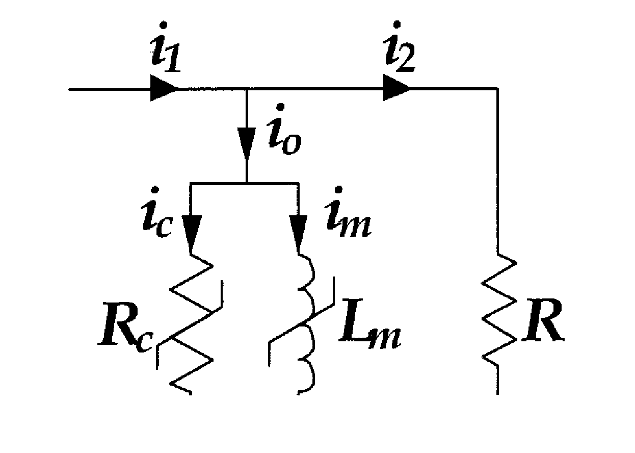
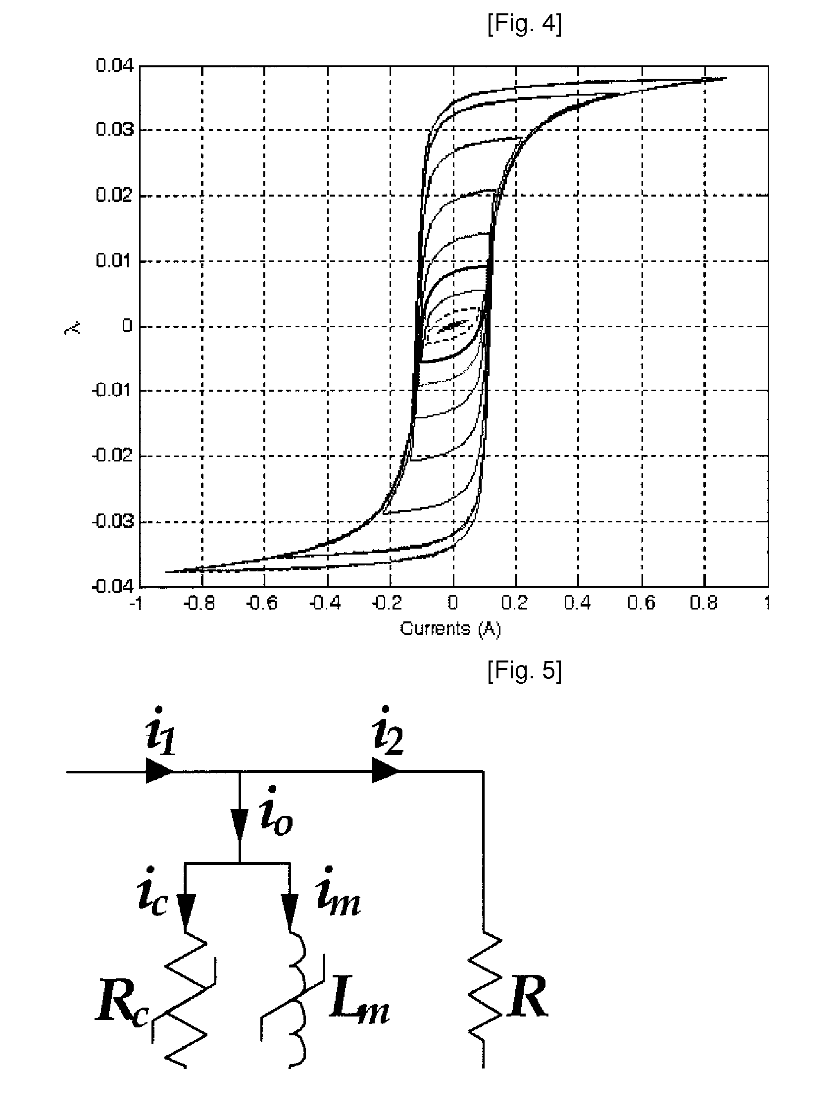
[0047]FIG. 5 is a diagram showing an equivalent circuit of a current transformer in which hysteresis characteristics of iron core are considered. Here, Rc and Lm represent core-loss resistance and magnetizing inductance, respectively, both of which have non-linear characteristics. Further, i0, ic, and im represent an excitation current, a core-loss current, and a magnetizing current, respectively, among which the relationship of i0=ic+im is established.[0048]The hysteresis characteristics of iron core are represented by a curve showing the relationship between magnetic flux and excitation current (λ-i0). FIG. 6 shows a hysteresis curve selected from the plurality of hysteresis curves of FIG. 4 (refer to the outer curve of two curves of...


PUM


Abstract

Provided an error compensating method for an instrument transformer, in which an error of an instrument transformer is compensated by reflecting hysteresis characteristics of iron core. When such error compensation is performed, a hysteresis loop indicating the relationship between magnetic flux and excitation current is not used as it is, but core-loss resistances and magnetic flux-excitation current curves are used, thereby achieving more precise compensation. According to the present invention, an error of an instrument transformer can be significantly reduced. Therefore, it is possible to manufacture an instrument transformer with high accuracy and to significantly reduce the size of the instrument transformer. Further, a material with high permeability does not need to be used in order to increase the accuracy.

Description

TECHNICAL FIELD[0001]The present invention relates to an error compensating method for an instrument transformer. In the error compensating method, an error of an instrument transformer is compensated by reflecting hysteresis characteristics of iron core. When such error compensation is performed, a hysteresis loop indicating the relationship between magnetic flux and excitation current is not used as it is, but core-loss resistances and magnetic flux-excitation current curves are used, thereby achieving more precise compensation.BACKGROUND ART[0002]In order to measure voltages and currents flowing in various electric equipments such as generators, power-transmission lines, transformers and the like, an instrument transformer is used. As for the instrument transformer, there are provided a voltage transformer for measuring a voltage and a current transformer for measuring a current. Depending on the use, the instrument transformer is divided into an instrument transformer for protec...

Claims


Application Information

Patent Timeline
IPC IPC(8): H01F38/28
CPCH01F27/422G01R35/02H01F27/427H01F27/24H01F38/28G01R15/18
Inventor KIM, YONG KYUNKANG, YONG CHEOLJANG, SUNG IL
Owner HANKOOK IED
Why Eureka
Try Eureka