Roll paper conveying apparatus, inkjet printer, and roll paper conveying method

a conveying apparatus and paper technology, applied in the direction of thin material handling, printing, filament handling, etc., can solve the problems of inability to achieve the desired stop position precision, the amount of paper to be fed to change, and the inability to control

Active Publication Date: 2011-09-01
RICOH KK
View PDF1 Cites 39 Cited by
  • Summary
  • Abstract
  • Description
  • Claims
  • Application Information

AI Technical Summary

Problems solved by technology

If the roll paper is directly pulled by carriage rollers, load fluctuation acts as a disturbance to the control of a conveying motor driving the carriage rollers, resulting in unstable control and therefore desired stop position precision may not be obtained.
In addition, if roll paper having a large moment of inertia is directly pulled by the carriage rollers, the carriage rollers might slip on the roll paper to cause the amount of paper to be fed to change, resulting in print deviation even if the conveying motor is precisely controlled.
In particular, when the machine is demanded to be compact, the movable range of the movable member tends to be restricted largely.
However, such control lacks responsiveness.
While the responsiveness of the control is expected to be improved by increasing the feedback gain, an increase in the feedback gain of the control of the roll paper driving motor that is to unwind and convey the roll paper having a large mass will result in oscillations and an unstable control.
Therefore, the feedback gain cannot be increased.
Therefore, in an inkjet printer required to feed the roll paper intermittently in units of the print width to the printing position, it is difficult to bring the movable member to the reference position within a paper feeding cycle even if the technology disclosed in Japanese Patent Application Laid-open No.
As a result, the movable member might be displaced out of the movable range, and collide with the inner surface of the housing of the machine or other components inside of the machine, for example, to damage the movable member, to cause vibrations or abnormal noise, or to smear the paper.

Method used


Image

  • Roll paper conveying apparatus, inkjet printer, and roll paper conveying method
  • Roll paper conveying apparatus, inkjet printer, and roll paper conveying method
  • Roll paper conveying apparatus, inkjet printer, and roll paper conveying method

Examples


first embodiment

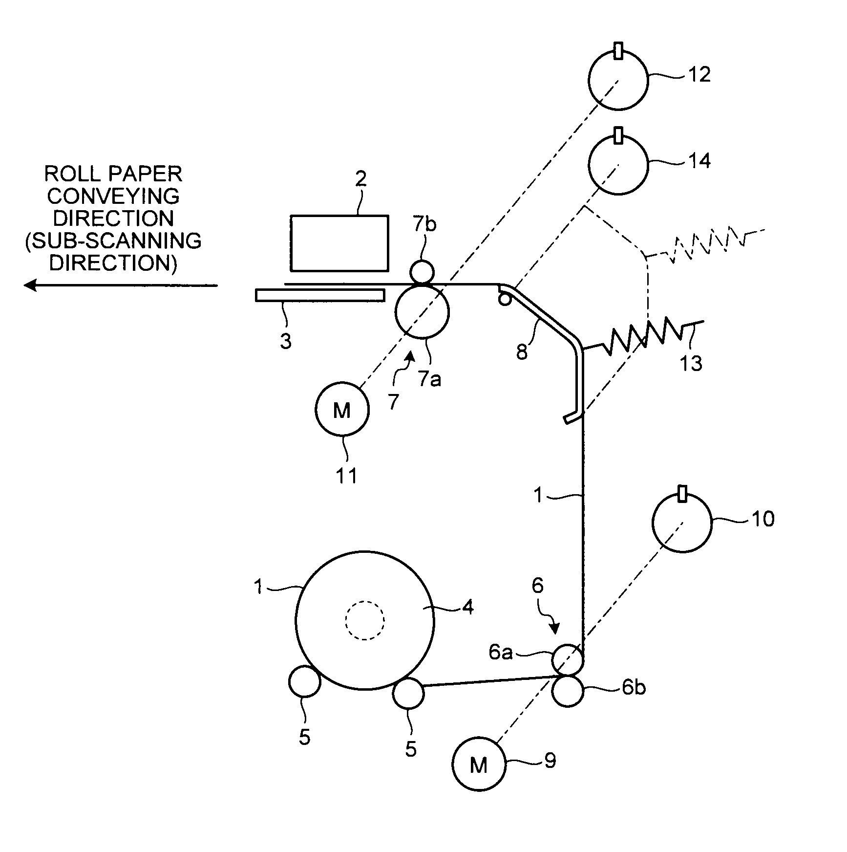
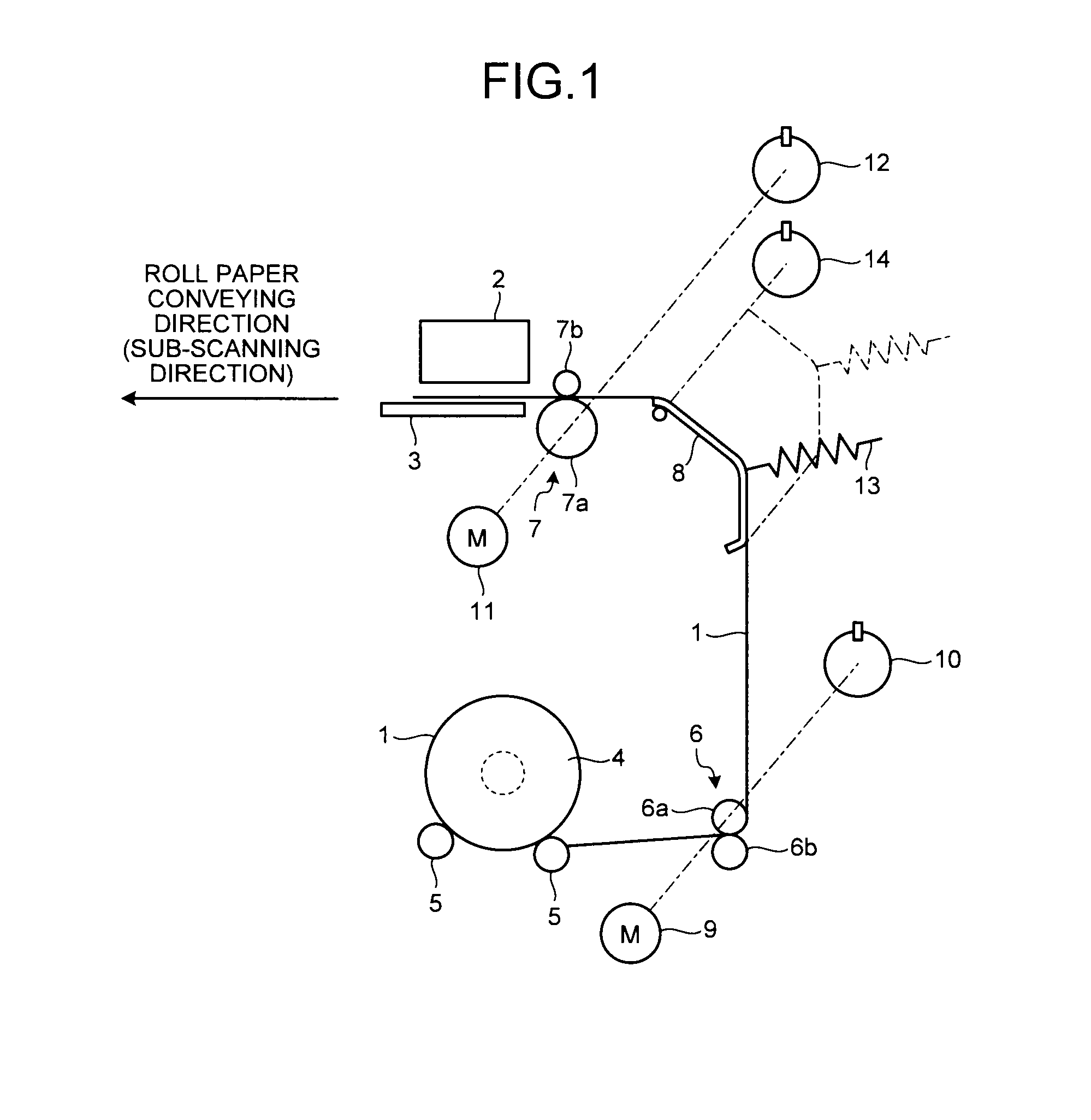
[0039]FIG. 1 is a schematic of a general structure of a paper conveying mechanism included in an inkjet printer according to a first embodiment of the present invention. The inkjet printer according to the first embodiment uses roll paper 1 as a printing medium to print an image, unwinds the roll paper 1 in units of a print width of a printer head 2, and intermittently feeds the roll paper 1 thus unwound along the sub-scanning direction. While the feeding operation of the roll paper 1 is being stopped, the printer head 2 scans the roll paper 1 on a platen 3 along the main-scanning direction (the direction perpendicular to the surface of the paper illustrated in FIG. 1) while applying ink thereto to print a desired image onto the roll paper 1.

[0040]A pair of flanges 4 holds the roll paper 1 used as the printing medium and wound in a roll from both ends thereof along the width directions, and the roll paper 1 held between the flanges 4 is set at a predetermined paper mounting position...

second embodiment

[0078]An inkjet printer according to a second embodiment of the present invention will be explained next. In the example explained in the second embodiment; a driving current supplied to the paper feeding motor 9 is detected; and a reference position of the movable member 8 is switched based on the detected driving current supplied to the paper feeding motor 9. Because the basic configurations of the paper conveying mechanism and the control system included in the inkjet printer are the same as those according to the first embodiment, components that are the same as those according to the first embodiment are given the same reference numerals, redundant explanations thereof are omitted hereunder, and characteristic parts of the second embodiment alone will be explained.

[0079]In the first embodiment, the reference position of the movable member 8 is a preset fixed value. The movable range of the movable member 8 is determined by the layout where the movable member 8 is arranged insid...

third embodiment

[0085]An inkjet printer according to a third embodiment of the present invention will now be explained. In the example explained in the third embodiment, the driving current supplied to the paper feeding motor 9 is detected, and the feedback gain of the paper feeding motor controller 25 and the parameters used in calculating the target speed (the target speed profile mentioned above) being changed in time series at every control cycle are switched based on a change in the detected driving current of the paper feeding motor 9. Because the basic configurations of the paper conveying mechanism and the control system included in the inkjet printer are the same as those according to the first embodiment, components that are the same as those according to the first embodiment are given the same reference numerals, redundant explanations thereof are omitted hereunder, and characteristic parts of the third embodiment alone will be explained.

[0086]As mentioned earlier, the responsiveness of ...


PUM

PropertyMeasurementUnit
driving currentaaaaaaaaaa

Abstract

A movable member encoder is used to detect the position of a movable member, and a correction value calculator calculates a correction value corresponding to the amount of displacement of the movable member from a reference position and the integration of the amount of displacement. The correction value calculated by the correction value calculator is then used in correcting a voltage instruction value output from a feed motor controller to a feed motor.

Description

CROSS-REFERENCE TO RELATED APPLICATIONS[0001]The present application claims priority to and incorporates by reference the entire contents of Japanese Patent Application No. 2010-043038 filed in Japan on Feb. 26, 2010.BACKGROUND OF THE INVENTION[0002]1. Field of the Invention[0003]The present invention relates to a roll paper conveying apparatus that conveys roll paper to a predetermined printing position, and also relates to an inkjet printer that uses the roll paper conveying apparatus.[0004]2. Description of the Related Art[0005]In a roll paper compatible printer that uses roll paper as a printing medium to print an image, the amount of the paper to be fed into a printing position must be controlled precisely because the load fluctuates as the amount of remaining roll paper being set changes. If the roll paper is directly pulled by carriage rollers, load fluctuation acts as a disturbance to the control of a conveying motor driving the carriage rollers, resulting in unstable contro...

Claims


Application Information

Patent Timeline
Patent Type & Authority Applications(United States)
IPC IPC(8): B41J2/01B65H23/10B65H23/185B65H23/16
CPCB65H23/16B65H2801/12B65H2553/51B65H2301/4493
Inventor SATOH, NOBUYUKIYAMANE, JUNKOBAYASHI, MASATOTAKI, NORIKAZUOKADA, TATSUHIKOHORIKAWA, DAISAKUSAWADA, DAISUKE
Owner RICOH KK
Why Eureka
Try Eureka